")
The clutch on a 1st gen Tacoma is generally known to be a very reliable part - often lasting 200K miles or more. Eventually though, they all wear out, necessitating replacement. There are several clutch options out there for the v6 (5VZFE) 96-04 Tacoma (or 96-02 4Runner, 95-98 T100, and 00-04 Tundra), and this guide will walk you through installation of any of those kits. Even with a 4-cylinder Tacoma, the process will be remarkably similar, though parts specifics may vary slightly.
As always, start by gathering parts and tools.
Parts
When installing a new clutch in a 5VZFE Tacoma or 4Runner, the first order of business is gathering parts. This can take a bit of time - as parts need to be acquired from various vendors - and it's a good idea to replace a few parts "around the clutch" at the same time the clutch is out as preventative maintenance, saving lots of labor.

The Clutch Itself
Replacing the clutch means replacing (or refurbishing) the following components: Clutch Disc (new), Clutch Pressure Plate (new), Flywheel (new or refurbish), Pilot Bearing (new), and Throwout Bearing (new). There are a couple ways to go about this - either with all Toyota OEM components, or with aftermarket replacements. Parts for each are outlined here, and while I often recommend OEM, in the case of the clutch, I went with the aftermarket option at the recommendation of several people more experienced than I am, in this particular situation.
Toyota OEM Parts
This is the most expensive route, and will give OEM-levels of performance. This is generally good for on-road applications; a better option for off-road is the Marlin Crawler 1,200 ft-lbs Heavy Duty Clutch Kit below.
- Toyota OEM Clutch Disc (31250-35352-84)
- Toyota OEM Pressure Plate (31210-35210-84)
- Toyota OEM Pilot Bearing (90363-12024)
- Toyota OEM Throwout/Release Bearing (31230-35110)
- Toyota OEM Clutch Flywheel (13405-62030)
Note: having not gone this route, I'm not sure if an OEM clutch disc comes with an alignment tool. If it does not, you'll need to pick one up here: Clutch Disc Alignment Tool for 5VZFE
A GREAT Aftermarket Option: Marlin Crawler 1,200 ft-lbs Heavy Duty Clutch Kit
- A Marlin Crawler 1,200lb Heavy Duty Clutch Kit. This kit came highly recommended by everyone I talked to, and while it is often out of stock at Marlin, I signed up for notifications when it came in stock and jumped on the kit when I got an email notification. It contains:
- Seco clutch disc with a robust double-spring design, excellent heat and wear resistance, and circumferential grooves & nickel coated splines
- Aisin 1,200 ft-lb heavy duty clutch cover/pressure plate with a heat-treated diaphragm spring, smooth pedal pressure for those long days on the trail, and a high torque rating for a sure engagement every time.
- A new pilot bearing
- A new throwout/release bearing
- A clutch disc alignment tool
- The only thing the Marlin Crawler kit doesn't include is a Flywheel, which should be replaced or refurbished whenever the clutch is replaced. Here, you have three options
- A new Toyota OEM Clutch Flywheel (13405-62030) is expensive but is manufactured to strict tolerances and quality control. This flywheel won't come with alignment pins, but you can easily pull the pins out of your existing flywheel to use on the new one, then get the original flywheel resurfaced for next time.
- A high quality aftermarket Flywheel like the Sachs Flywheel for 5VZFE (NFW6939). This flywheel is significantly less expensive, and comes with alignment pins.
- Resurfacing your existing flywheel - if you go this route, look for a vendor that will grind your flywheel, and get the step ground to between .020" and .026" (20- to 26-thousandths of an inch)
As of January 2023, Marlin is - unfortunately - no longer selling this clutch kit. For six months, I didn't have another great kit to offer, but after having a buddy run the EXEDY 16805 Racing Clutch Kit since early 2023, it seems to be another great option, with specs that are very similar to the Marlin kit.
Another GREAT Option: EXEDY 16805 Racing Clutch Kit
- EXEDY 16805 Racing Clutch Kit for 5VZFE. This kit has specs that are similar to the Marlin kit, with the following key points:
- Clutch disc with a full face organic clutch rather than a ceramic puck style on lighter-duty discs
- A 1,985 ft-lb heavy duty clutch cover/pressure plate.
- A new Nachi pilot bearing
- A new Nachi throwout/release bearing
- A clutch disc alignment tool
- The only thing the EXEDY kit doesn't include is a Flywheel, which should be replaced or refurbished whenever the clutch is replaced. Here, you have three options
- A new Toyota OEM Clutch Flywheel (13405-62030) is expensive but is manufactured to strict tolerances and quality control. This flywheel won't come with alignment pins, but you can easily pull the pins out of your existing flywheel to use on the new one, then get the original flywheel resurfaced for next time.
- A high quality aftermarket Flywheel like the Sachs Flywheel for 5VZFE (NFW6939). This flywheel is significantly less expensive, and comes with alignment pins.
- Resurfacing your existing flywheel - if you go this route, look for a vendor that will grind your flywheel, and get the step ground to between .020" and .026" (20- to 26-thousandths of an inch)

A (Cheaper) Aftermarket Option: Sachs Clutch Kit
If you can't wait for a Marlin Crawler kit, and don't want to pay for a Toyota OEM clutch, I've heard good things about the SACHS K70165-01 Transmission Clutch Kit For 5VZFE. Like the Marlin kit, you'll need to purchase a flywheel separately, and have similar options:
- SACHS K70165-01 Transmission Clutch Kit For 5VZFE - this kit will fit the following vehicles with a 5VZFE (v6) engine:
- 96-04 Tacoma
- 98-02 4Runner
- 95-98 T-100
- 00-04 Tundra
- Flywheel options:
- A new Toyota OEM Clutch Flywheel (13405-62030) is expensive but is manufactured to strict tolerances and quality control. This flywheel won't come with alignment pins, but you can easily pull the pins out of your existing flywheel to use on the new one, then get the original flywheel resurfaced for next time.
- A high quality aftermarket Flywheel like the Sachs Flywheel for 5VZFE (NFW6939). This flywheel is significantly less expensive, and comes with alignment pins.
- Resurfacing your existing flywheel - if you go this route, look for a vendor that will grind your flywheel, and get the step ground to between .020" and .026" (20- to 26-thousandths of an inch)
Parts Around the Clutch
Besides the clutch, the following should be replaced when the clutch is out of the truck, since it would need to be removed to replace them anyway:
- A new Toyota OEM Rear Main Seal (90311-A0027) - if the transmission is being separated from the engine anyway, now's a good time to replace the rear main engine seal. Often times, the original will be leaking slightly anyway.
- A Marlin Crawler Heavy Duty Shifter Seat & Socket - to replace the shifter seats and socket for the transmission and transfer case shifters, since they had to be removed anyway.
Tools
Replacing the clutch generally involves standard tools, with a couple of exceptions.
- For various lifting/supporting operations
- Socket Set that includes both shallow and deep sockets in the following sizes (this is a good set): 10mm, 12mm, 14mm, 17mm, 19mm.
- Several socket extensions and socket wobble extensions of various lengths, measuring at least 40" in overall length and with the ability to "bend" over that distance. See photo below for an example.
- Socket wobble joints (usually included in a socket set)
- Set of metric wrenches (this is a good set) in the following sizes: 10mm, 12mm, 14mm, 17mm.
- Pick tool set
- High temp grease for greasing various components.
- General grease in a grease gun - for removal of pilot bearing from crankshaft.
- Clutch Disc Alignment Tool for 5VZFE - may already be included with the clutch disc (or kit) depending on which parts option is chosen
- Needle nose pliers - for snap ring and electrical plug removal.
- 90º Needle Nose Pliers - for snap ring and electrical plug removal.
- Philips Screw Driver - for interior removal.
- Dead blow mallet
- Torque wrench
Doing the Job
Doing this job entails removal of several components, ultimately allowing removal of the transmission (and transfer case) from the truck so that the clutch can be replaced. Then, reinstallation of those components.
Initial Prep
- Disconnect the battery.
- Jack up the front passenger side of the truck; support on a jack stand as high as possible.
- Remove the front passenger wheel.
- Chalk the rear tires so the truck will not roll, and place the front passenger wheel under the front passenger lower control arm (LCA) as an added layer of protection.
- Ensure that the truck is not in gear.
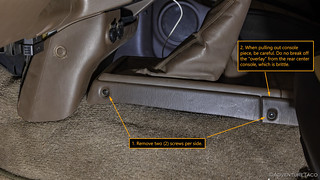
Remove the Center Console Trim
Note: this procedure varies for various vehicle trims and years. Shown here is a 2000 Tacoma, 5VZFE M/T with a j-shift transfer case.
- Remove the clips securing the center lower cover by pressing in on the center to release them.

- Pull the cover out just far enough to unplug the 12v outlets, and then remove and set aside the cover.
- Use a Philips screwdriver to remove the four screws that secure the shifter assembly trim and lift the trim up and out of the way, being careful not to break the center console trim tabs.
- Use a Philips screwdriver to remove the four screws that secure the rubber boots covering the shifter assembly, then lift the rubber boots up and out of the way.

Remove the Shift Levers
- Using a small pick tool, pry the rubber boots that connect the shift levers to their bases away from the bases.

- Using a pair of needle nose or 90° pliers, release the retaining clip on the transfer case shifter, and pull the shifter out of the socket.

- Using two fingers, press down on the retaining ring of the transmission shifter, and rotate it counter-clockwise until it releases and is pushed up by the internal spring. Remove the shifter from its socket.

- Using a pick tool, remove the shifter bushings and rubber spacers from both the transfer case and transmission mounts.

- Using a shop rag, and being careful to not drop disintegrated bushing pieces or dirt into the cases, clean out any residue left in the shifter mounts.
- Fill each mounting hole with a shop rag, to keep material out of them for the rest of the project.
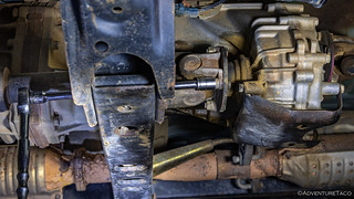
Disconnecting and Removing the Front Drive Shaft
- Shift the transfer case into 4-Lo and put the vehicle into gear (or for a A/T, into park) in order to keep the front drive shaft from spinning while you disconnect it.
- Using a paint pen, make a witness mark on the slip joint of the front drive shaft. Note: It's important to keep the drive shaft aligned, as it is balanced prior to installation. You shouldn't need to separate the two halves, but the witness mark ensures that you can get them back together if you accidentally do.

- Using a paint pen, make a witness mark at each end, so that the flanges can be re-attached to the front diff and transfer case in the same orientation.
- Using a 14mm socket, loosen and remove the four (4) nuts that secure the front drive shaft to the studs protruding from the transfer case flange. Note: to access all of the nuts, you may need to rotate the front drive shaft, by shifting the transfer case out of 4-Lo.
- Using a 14mm socket and 14mm wrench, loosen and remove the four (4) bolts that secure the front drive shaft to the front diff flange. Note: to access all of the bolts, you may need to rotate the front drive shaft, by shifting the transfer case out of 4-Lo.
- With all fasteners removed from both ends of the drive shaft, support the shaft while striking it from the bottom - as near the front flange as possible - with a rubber dead-blow mallet. This will free up the front end and allow you to lift the drive shaft up, then slightly forward to remove it from the studs on the transfer case flange.
- Set the front drive shaft aside.
Disconnecting the Rear Drive Shaft
With an extended cab or double cab Tacoma, the rear drive shaft has two pieces, supported in the middle by the center bearing. Rather than remove only the front piece, it's easier to drop the center bearing, leaving the two halves of the shaft connected. On a single cab (or 4Runner), the drive shaft is a single piece, and like the front drive shaft you must disconnect it from the rear diff, in order to remove it from the studs on the transfer case flange.
- Shift the truck into neutral.
- Using a floor jack under the rear diff, jack up the rear end until at least one of the tires can spin freely.
- Engage the emergency brake to keep the rear wheels - and rear drive shaft - from spinning as you work on it.
- Using a paint pen, make a witness mark on the slip joint of the rear drive shaft. Note: It's important to keep the drive shaft aligned, as it is balanced prior to installation. You shouldn't need to separate the slip joint, but the witness mark ensures that you can get it back together if you accidentally do.
- Using a paint pen, make a witness mark at each end, so that the flanges can be re-attached to the rear diff and transfer case in the same orientation.
- Using a 14mm socket, loosen and remove the four (4) nuts that secure the rear drive shaft to the studs protruding from the transfer case flange. Note: to access all of the nuts, you may need to rotate the rear drive shaft, by releasing and then resetting the parking brake.
- With an Extended Cab or Double Cab Tacoma:
- Using a paint pen, mark the bottom of the center bearing, to make later installation easier.
- Set a jack stand under the center bearing, at the lowest height possible.
- Using a 14mm socket, loosen and remove the two (2) bolts that secure the center bearing to the frame crossmember. Note: be sure to support the drive shaft as you remove the second bolt, so it doesn't fall.
- Carefully place the center bearing onto the jack stand. Note: the slip joint should extend slightly at this point, but it should not come apart.

- Support the shaft while striking it from the bottom - as near the front flange as possible - with a rubber dead-blow mallet. This will free up the front end and allow you to pull the drive shaft slightly back, compressing the slip joint and removing it from the studs on the transfer case flange.

- With a Single Cab Tacoma or 4Runner:
- Using a 14mm socket and 14mm wrench, loosen and remove the four (4) bolts that secure the rear drive shaft to the rear diff flange. Note: to access all of the bolts, you may need to rotate the rear drive shaft, by releasing and then resetting the parking brake.
- With all fasteners removed from both ends of the drive shaft, support the shaft while striking it from the bottom - as near the front flange as possible - with a rubber dead-blow mallet. This will free up the front end and allow you to lift the drive shaft up, then slightly forward to remove it from the studs on the transfer case flange.
- Set the drive shaft aside.

Removing the Sway Bar
For photos of removing the sway bar, see Remove the sway bar and sway bar end links. If you will be reinstalling your sway bar, now may be a good time to replace your sway bar and end link bushings as well with an Energy Suspension kit:
- Tacoma - kit 8.5118 w/27mm bushings (black | red)
- 4Runner - kit 8.5117 w/26mm bushings (black | red)
- Use a 14mm socket to remove the nut on the top of the sway bar end link.
- Remove the washer and bushing and set them aside.
- Repeat for the opposite side.
- Use a 12mm socket to remove the two (2) bolts securing the sway bar brackets to the frame.
- Repeat for the opposite side.
- Remove the sway bar.

Disconnecting Wiring Harnesses from the Transmission and Transfer Case
The wiring harness varies from year to year and truck model to truck model. The key to this process is ensuring that the entire wiring harness is separated from the transmission and transfer case prior to lowering them from the truck, so that no wires/connectors/clips are broken in the process.
- To disconnect the wiring harness, start where the wiring harness terminates at the rear of the transfer case on the passenger side at the speed sensor, then, work your way towards the front of the harness.
- At each location where the harness is attached to either the transfer case or transmission, unplug the connector, remove a bolt that secures the bracket, or release the clip that secures the harness.
- Once the entire harness is free, pull it to the front driver side of the transmission. This ensures that you can store it out of the way for the remainder of the process.
Note: to access the connectors, clips, and brackets, you will need to access the harness from both the driver and passenger side, as well as through the shifter opening in the cab of the truck.
Removing the Clutch Slave Cylinder
- Remove the two (2) 12mm bolts that secure the hard slave cylinder hydraulic line to the transmission. Label and set aside. Note: a bracket securing the hydraulic line to the bellhousing is captured by one of the 17mm bolts that secures the bellhousing to the engine. It will be removed later.
- Remove the two (2) 12mm bolts that secure the clutch slave cylinder the transmission. Label and set aside.

Note: be sure to be aware of these components as the transmission is lowered, so that it does not get caught up on the clutch slave cylinder or hydraulic lines.
Disconnecting the Starter
- Remove the plastic cover from the power connector.
- Disconnect the nut securing the power connector using a 12mm wrench.
- Disconnect the electical connector by pushing up on the connector tab and pulling the connector toward the front of the truck.

- Supporting the starter with your hand, remove the two (2) 14mm bolts that secure the starter using a deep socket. Label the bolts and set aside. Note: the upper bolt is shorter than the bottom bolt.

- If the starter is hard to remove, wedge it out of the way in a crevice in the engine bay.
4Runner Only: Disconnect the Exhaust Manifold to Enable Bellhousing Clearance
- Use penetrating oil and heat on the front exhaust manifold nuts to make removal easier. Note: even doing this, you may break one of more of exhaust studs.
- Using wrenches or sockets as necessary, remove the three (3) 14mm nuts from their respective studs in order to separate the front exhaust connection, making room to remove the bellhousing.
Disconnect the Transmission Bellhousing from the Engine
There are six (6) 17mm bolts that secure the transmission bellhousing from the engine:
- Two (2) are easily accessible on the passenger side
- Two (2) are easily accessible on the driver side
- Two (2) are difficult to access on the top
Note: several of these bolts are different lengths, and so labelling and maintaining their position is important.
Note: after removing these bolts, the transmission will still be held in place by two alignment pins, but you should be careful to not move it around too much while it is unbolted, and before it is supported by a transmission jack.
- Using a 17mm socket and several extensions - long enough to reach to the rear of the transfer case - remove the two bolts at the top of the bellhousing. Label each bolt and set aside.

- Using a deep 17mm socket, remove the two (2) bolts on the passenger side. Label each bolt and set aside.
- Using a 17mm socket and any necessary extensions, remove the two (2) bolts on the driver side. Label each bolt and set aside.

Removing the Transmission Access Plate
- Use a 12mm ratchet to remove the four (4) bolts that secure the access plate to the front of the transmission. Label and set aside the bolts and access plate.


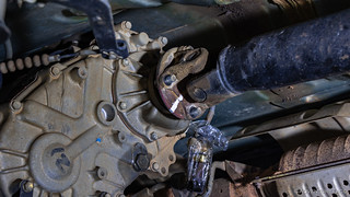
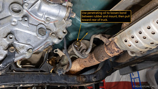
Removing the Transmission Crossmember and Transmission
- Support the transmission and transfer case with a transmission jack.

- Tacoma, T-100, Tundra only: Release the rubber retainer that connects the transmission crossmember to the exhaust by spraying the hanger with penetrating oil and pulling the rubber retainer towards the rear of the truck.
- Remove the four (4) 12mm bolts that secure the transmission mount to the transmission cross member, through the bottom of the crossmember. Label and set aside. Note: this means that the transmission mount remains attached to the transmission, which is fine.
- Using a 14mm socket, and a 14mm wrench to hold the corresponding nuts, remove the four (4) 14mm bolts that secure the crossmember to the frame.

- Remove the crossmember and set aside.
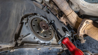
- Using the transmission jack to support the transmission, separate the transmission from the engine. Note: the pilot bearing will still have a pressure fit between the crankshaft and transmission input shaft, so it may be necessary to use (carefully) pry bars in order to complete the separation.
Warning: the clutch disc and pressure plates are generally made of really nasty carcinogenic material (asbestos, etc). Wear a face mask and do not use compressed air or tools that will stir up dust.
Removing the Old Pressure Plate, Clutch Disc, and Flywheel
Warning: the clutch disc and pressure plates are generally made of really nasty carcinogenic material (asbestos, etc). Wear a face mask and do not use compressed air or tools that will stir up dust.
- Using a 12mm socket, remove the six (6) 12mm bolts that secure the pressure plate to the engine, supporting the pressure plate as the last bolt is removed.

- If necessary, use a mallet and pry bar to break the pressure plate loose. Note: If you rotate the pressure plate, only rotate in the counterclockwise direction, which rotates the engine in a clockwise direction.
- Remove the pressure plate. Note the orientation and set it aside.
- Remove the clutch disc. Note the orientation and set it aside.

- Using an impact wrench, remove the eight (8) 14mm bolts that secure the flywheel, being sure to support the flywheel as the last bolt is removed.

- Remove the flywheel. Note the orientation and set it aside.
Replacing the Rear Main Seal
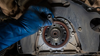
- Using the Lisle seal puller, remove the rear main seal. Note: be careful to not score the crankshaft or seal race during this process.
- Lubricate the new rear main seal, as well as the crankshaft and seal race with a thin layer of grease.
- Insert the new main seal into position. Use a rubber mallet and a brass drift or small socket to drive it into position. Note: use light taps on alternating sides of the seal to drive the seal until it is flush with the polished surface of housing.
Removing the Pilot Bearing
The pilot bearing should remain wedged into to the end of the crankshaft (engine side) when the transmission is removed. Removing it can be done with a specialized puller, but it's relatively easy to do it with tools on hand as well.
- Find the largest diameter bolt you have that will fit into the center hole of the pilot bearing. If it is not a relatively good fit, wrap it with electrical tape until it slides easily, but doesn't have a lot of open space.
- Using general grease in a grease gun, pump as much grease into the center hole of the pilot bearing as possible, filling the void behind the pilot bearing. Note: bread can also be used in place of grease - as shown in the video below - though I've found grease to work better.
- Using a hammer, tap the untaped end of the bolt into the center hole of the pilot bearing until it bottoms out. Note: this should be only one or two taps.
- After repeating steps 2 and 3 several times, you should notice the pilot bearing beginning to press out of the crankshaft. Note: this is hydraulic pressure created by packing the grease/bread behind the bearing that is pushing the pilot bearing out.
.
.
Installing the new Pilot Bearing
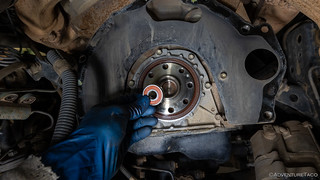
- Ensure that the race into which the pilot bearing will be installed is cleaned of any bread or grease that was used to eject the original pilot bearing, as well as any other contaminants.
- Spread a little grease on the outer race of the pilot bearing, and the race in the crankshaft, and then use a socket that matches the outer diameter of the pilot bearing to slowly tap the pilot bearing evenly into the race in the crankshaft until it bottoms out and is fully seated. Note: be sure that the socket is supported by the outer metal sleeve of the bearing, and not the rubber seal or inner sleeve, as pressing from those areas can ruin the bearing.
- Spread a little grease on the inner race of the pilot bearing, to accept the transmission input shaft when it is installed later.
Removing the Throwout Bearing
- Remove the rubber boot that seals the clutch fork where it enters the transmission. Note: this boot just pops out of the transmission.
- By pressing in and pulling away from the "handle" of the clutch fork, remove the clip that secures the throwout bearing to the clutch fork
- Remove the throwout bearing from the transmission input shaft by sliding it forward.
- Remove the clutch fork from the transmission.

Installing the new Throwout Bearing
Note: installing the throwout bearing and clutch fork must take place inside the bellhousing.
- Spread some high temperature grease where the wings of the throwout bearing contact the tips of the clutch fork.
- Spread some high temperature grease where the clutch fork pivots on a metal post in the transmission bellhousing.

- Insert the clutch fork into the transmission bellhousing and onto the pivot point. Note: ensure that the spring that secures the clutch fork on the pivot is properly seated.
- Insert the throwout bearing onto the transmission input shaft and into the clutch fork.
- Secure the throwout bearing to the clutch fork by capturing the "wings" of the throwout bearing with the spring that seats into the clutch fork.
Installing the New Flywheel
Note: at this point, cleanliness is key as the surfaces that will be making contact will slip if grease or other contaminants are present. Put on new gloves to keep surfaces oil and dust free.
- Place the flywheel into position and insert the eight (8) of the 14mm bolts to secure it into place. Hand tighten the bolts only at this point, using a star pattern.
- In order to keep the flywheel from turning while the bolts are torqued to spec, have a helper hold the crank bolt (at the front of the engine) with a 19mm socket. This will keep the engine from turning backwards as the bolts are torqued.
- Use a torque wrench in a star/crisscross pattern, slowly bring the eight (8) 14mm bolts up to 63 ft-lbs of torque.

Clean the Surface of the Flywheel
Note: at this point, cleanliness is key as the surfaces that will be making contact will slip if grease or other contaminants are present. Put on new gloves to keep surfaces oil and dust free.
- Using brake cleaner and brand new, oil free shop rags, clean the flywheel surface several times, until no contamination is visible on a clean shop rag.
Installing the New Clutch Disc and Pressure Plate
Note: orientation of the new clutch disc is important. In most cases, the clutch kit will come with an indication of which surface faces forward.
- Ensure the proper orientation of the clutch disc. On a 5VZFE, the side of the clutch disk that protrudes farther goes towards the flywheel.

- Insert a clutch disc alignment tool into the clutch disc and then into the pilot bearing, thereby aligning the clutch disc and flywheel.
- Lift the pressure plate into place, aligning the smaller holes with the alignment pins on the flywheel. Note: when doing this, also ensure that the holes for the bolts are aligned.
- Insert and finger tighten the eight (8), 12mm pressure plate bolts.
- Using the clutch disc alignment tool, ensure that the clutch disc is perfectly centered between the flywheel and pressure plate by moving the alignment tool so that it is centered in all directions.
- Slowly torque the pressure plate bolts to 14 ft-lbs over the course of three to four passes. Note: Do not use a standard star/crisscross pattern of torquing these bolts, use the order shown below where the bolts next to the alignment pins are tightened more frequently than the bolts that are not next to alignment pins.

Installing the Transmission
- Spread a very small amount of high temperature bearing grease on the clutch splines. Note: this should be a very small amount, as you don't want any excess being thrown off the splines and contaminating the clutch components.
- Use a clean shop rag to clean off nearly all of the high temperature bearing grease from the clutch splines, so that only an extremely thin residual coating is left.
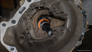
- Using the transmission jack, slowly move the transmission into place, aligning the alignment dowels. Note: at this point, it is unlikely that you'll be able to completely connect the transmission and engine, as the transmission input shaft must be slid into the pilot bearing on the engine side, but if the clutch disc is properly centered, you should be able to get the transmission bellhousing and engine within about ¼" of each other.
- When the alignment pins are aligned, insert the two (2) 17mm bolts on the driver side and two (2) 17mm bolts on the passenger side of the transmission. Finger tighten.
- Alternating sides, slowly tighten the four (4) 17mm bolts in order to pull the transmission and engine together, while at the same time, pressing the transmission input shaft into the pilot bearing that is seated in the crankshaft. Tighten, but do not torque.
- Install the top two (2) 17mm bolts until they are tight. Do not torque.
- Move the transmission crossmember into place until the plastic alignment pin drops into the crossmember.
- Install the four (4) 14mm bolts and nuts to secure the crossmember to the frame. Note: the bolts insert from the front, and nuts are on the rear. Tighten, but do not torque.
- Remove the transmission jack from under the vehicle.
- Torque the six (6) 17mm bolts that secure the transmission bellhousing to the engine to 53 ft-lbs in a star pattern.
- Torque the four (4) crossmember bolts to 48 ft-lbs.
- Install and torque the four (4) 12mm bolts that secure the transmission mount to the crossmember. Torque spec: 13 ft-lbs.
4Runner Only: Connect the Exhaust Manifold
- Using wrenches or sockets as necessary, install the three (3) 14mm nuts to their respective studs in order to pull the front exhaust connection back together
- Torque to 46 ft-lbs.
Tacoma, T-100, Tundra Only: Connect the Exhaust Hanger
- Push the rubber retainer onto the bracket to secure the exhaust to the transmission crossmember.
Install the Starter
- Supporting the starter with your hand, hand tighten the two (2) 14mm bolts that secure the starter using a deep socket. Note: the upper bolt is shorter than the bottom bolt.
- Torque the two (2) 14mm bolts to 29 ft-lbs.
- Connect the electrical plug.
- Secure the nut for the power connector using a 12mm socket.
- Install the plastic cover from the power connector.
Installing the Clutch Slave Cylinder and Hydraulic Lines
- Install the two (2) 12mm bolts that secure the hard slave cylinder hydraulic line to the transmission. Torque to 9 ft-lbs.
- Install the two (2) 12mm bolts that secure the clutch slave cylinder the transmission. Torque to Torque to 9 ft-lbs.
Installing the Wiring Harness
The wiring harness varies from year to year and truck model to truck model. The key to this process is ensuring that everything that was disconnected is reconnected.
- To reconnect the wiring harness, start at the front driver side of the harness and work your way to the rear of the transfer case on the passenger side.
- At each location where the harness is attached to either the transfer case or transmission, connect the connector, insert a bolt that secures the bracket, or insert the clip that secures the harness.
Note: to access the connectors, clips, and brackets, you will need to access the harness from both the driver and passenger side, as well as through the shifter opening in the cab of the truck.
Installing the New Shifter Bushings
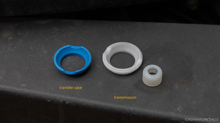
- Replace the plastic socket on the transmission shift lever with the one from the kit by prying the old one off and pressing the new one on.
- Place the new transmission shifter bushing upside down into the transmission shifter hole with the divots in the busing aligned with the pins in the hole.

- Pivot the bushing 180 degrees on the pins and it will snap into place.
- Place the new transfer case shifter bushing upside down into the transfer case shifter hole with the divots in the busing aligned with the pins in the hole.
- Pivot the bushing 180 degrees on the pins and it will snap into place.
Installing the Shift Levers
- Insert the transmission shift lever into the transmission socket, ensuring that it seats correctly into the transmission.
- Using two fingers, press down on the retaining ring of the transmission shifter, and rotate it clockwise until catches on the two pins on the inside of the socket, holding the shifter in place.
- Insert the transfer case shifter into the transfer case socket, ensuring that it seats correctly into the transfer case.
- Using a pair of needle nose or 90° pliers, reseat the retaining clip on the transfer case shifter, holding the shifter in place.
- Ensure that both shifters are shifting correctly.
Installing the Shift Levers and Center Console Trim
- Place the rubber boots over the shifters and secure it with four (4) Philips screws.
- Place the shifter assembly trim over the rubber boots and secure it with four (4) Philips screws.
- Place the center lower cover nearly in place and reconnect the 12v power receptacles.
- Clip the center lower cover into place.
- Insert the two clips into the sides of the center lower cover, and secure them.

Connecting the Rear Drive Shaft
Before installing the rear drive shaft, ensure that the witness marks on the slip yoke are aligned.
- If your truck has a center bearing:
- Place a jack stand under the center bearing when the slip yoke of the rear drive shaft is completely collapsed.
- Place the front end of the rear drive shaft over the studs on the transfer case flange and secure loosely with four (4) 14mm nuts and washers.
- Raise the center bearing into position and secure loosely with two (2) 14mm bolts and washers. Note: ensure correct orientation of the center bearing bracket.
- Engaging the emergency brake as necessary, torque the four (4) 14mm nuts at the transfer case flange to 54 ft-lbs.
- Torque the two (2) 14mm bolts securing the center bearing to 27 ft-lbs.
- If your truck has no center bearing:
- Support the rear end of the drive shaft approximately 12" off the ground with a jack stand.
- Place the front end of the rear drive shaft over the studs on the transfer case flange and secure loosely with four (4) 14mm nuts and washers.
- Align the rear end of the rear drive shaft with the rear diff flange and secure loosely with four (4) 14mm bolts, nuts, and washers.
- Engaging the emergency brake as necessary, torque all eight (8) 14mm fasteners to 54 ft-lbs. Note: when torquing nuts to studs, tighten the nuts. When torquing bolts with nuts, tighten the bolts.
Installing the Front Drive Shaft
Before installing the front drive shaft, ensure that the witness marks on the slip yoke are aligned.
- Place the rear end of the front drive shaft over the studs on the transfer case flange and secure loosely with four (4) 14mm nuts and washers.
- Align the front end of the front drive shaft with the front diff flange and secure loosely with four (4) 14mm bolts, nuts, and split washers.
- Engaging 4-Lo as necessary, torque all eight (8) 14mm fasteners to 54 ft-lbs. Note: when torquing nuts to studs, tighten the nuts. When torquing bolts with nuts, tighten the bolts.
Adjusting the Clutch Pedal
Generally, adjusting the clutch pedal is not necessary. However, if you need to do it, the procedure is as follows:

Finishing Up
- Reattach the passenger front wheel. Torque to 89 ft-lbs when vehicle is under its own weight.
- Reconnect the battery.
That's it! When breaking in your new clutch, drive gently for the first 500 miles or so.
Thank you so much for this detailed and helpful write up. Made replacing my clutch a breeze! Much needed.
Glad it helped Gabriel! I've gotten so much help from other folks, it's always nice to be able to give back a bit! ?
Thanks for the post, took all the guess work out of this job. The step by step instructions with torque specifications made for a quick and easy clutch replacement.
Can you elaborate on why the passenger tire needs to be removed (clearance, access to something)? It looks like everything should be accessible with it on. Would it be possible to leave the truck on wheels while doing this?
Hey Russell, I removed the passenger tire as it enables easier access/removal of various other components such as the starter. Depending on your engine, you might not need to do that, but on the 5VZFE, having that extra room/access point through the wheel well makes things a lot more convenient.
This is one good wright up step by step. Thank you! When I bought my clutch kit, the clutch disc side said (flywheel side), and it's on the flat side. Your wright up, said the protrudes side. Is it because of the engine type 5VZ-FE and 3R2-FE?
thanks
Hey Pat, glad you liked the write-up. You're correct that the flat side of the clutch disc points in different directions on the 5VZ-FE and 3R2-FE. I don't know why that is, but it so it is! ?
Any tips for getting the manual transmission to mate back up. Having the hardest time getting it together
Most of the time, difficulty in getting the MT mated back up with the engine is due to the clutch disk not being perfectly centered (which, even when you use the installation tool, is an easy situation to end up in). My recommendation would be to pull off the clutch disk and try installing it again, making sure that it really is centered, so that the transmission input shaft can slide - as easily as possible - into the throw out bearing. At that point, it's still not easy to fully mate to the two machined surfaces, but you can get the alignment pins started, and pull the two components together by tightening the bolts in a star pattern.
I can't tell you how many folks I've seen get the clutch plate "close" but just far enough out that it looks OK from underneath while still making it really hard to get the input shaft seated. Even if you are able to suck them together at that point, you'll destroy the throw out bearing quickly, so you want to get this step right.
Good luck!
With the marlin HD clutch kit unavailable, how does someone find the 1,200 ft-lb clutch cover/pressure plate from aisin. I have looked everywhere I know.
Hi Robert, it's a bummer that Marlin stopped selling their kit for sure. I haven't posted a good alternative before now because I haven't really felt comfortable recommending something else. However, for the last six months, one of my buddies has been running the EXEDY 16805 Racing Clutch Kit with great success. Specs on it are similar (in fact, slightly better) than the Marlin kit, and given that it also has a full face organic clutch rather than a ceramic puck style one, it's more suited for off-road use than other options out there. Hope that works for ya!
Excellent procedure, thanks for taking the time and care to be thorough.
For what it's worth, per the mfr, the ClutchMax Pro Stage 2 disc must be installed in the opposite orientation with the hub side toward the transmission even though it will also fit in the stock orientation and it has no directional markings.
Hope that saves somebody the time and grief I went through.
Hey, I’m in the process of swapping in a manual on an 02’ Tacoma and the transmission access plate mentioned early in the write up is something I’ve never heard of or seen? Is this an essential component to the transmission? Thanks
It's not a "mechanically functional" part, it's just a cover, but you certainly want to have one, just to keep a lot of crap out of the flywheel/trans.[Without it, you'll be scooping up water, dirt, mud, etc.
I've always called it the access plate, but it looks like Toyota calls it the Flywheel Housing Seal. Not cheap, but not that bad, either.
And, same part for MTs from '95.5-'04. 👍
Nice technical write up to be sure, thanks for sharing.
I've a hybrid setup 98 2rz block,w/ a 3rz Head>W56 Tranny. My Exedy Kit, (regarding which way clutch faces), really shy on that aspect, only thing I see that makes "some" sense is this:, T/M side, any guess as to that mess?
You suppose it means (T)rans/(M)ission side, or, (T)o/(M)otor?
Yes I'm still digging throu the internet. Thanks for the time.
Thank you so much! This made this job very doable for me. Great explanation and accuracy!
Awesome, glad it was useful for ya!
Do you recommend replacing the pivot bolt for the clutch fork if installing a new clutch fork?
I didn't replace mine; but then, I didn't replace my clutch fork, either. I suppose I'd have a look at it to determine the type of wear, and if I was replacing the clutch fork anyway, I'd probably look at replacing the bolt, under the thinking that "if the fork is worn, there might have been some stresses on the bolt, too."
Hi there, great write up. I also have a question about the access plate (flywheel housing). im going through a cluth replacement on a 99 Tacoma, SR5 3.4l. im currently about to remove the cross member and lower the transmission.
1. Is there a reason why the access plate is removed prior to removing the transmission? seems like it would be easier to remove after the trans is out. its kind of hard to get around the steering rack to remove while in place.
2. I dont see in your instructions when to reinstall the access plate. does this need to haopen before or after reinstalling the trans?
Thanks!
Hey Greg, sorry for the slow-ish response, been out on an adventure the last few days. My answers to your questions are going to be a bit on the lame side... you've been warned.
1. I don't recall why I removed the access plate prior to removing the trans; I think I did it either (a) because there seemed to be a lip (or something) that was catching when I was trying to remove the trans or (b) because I was already under there disconnecting the starter.
2. I also son't remember when I put it back on. I'd base your decision for this on when you're able to take it off. If you can get the trans out with it still attached, reattach it prior to installing the trans; likewise, if you find a reason to take it off when I did, put it on after trans installation.
And, thanks for pointing out that I missed reinstallation. Please let me know what you find, and I'll updat the guide accordingly! 👍
99 TACOMA 3.4 SR5 When reinstalling the access cover to the flywheel has it been determined if it can be installed befor the bellhousing is slid back in place ?? The 4 bolts that hold it in place cannot be reached by hand. One bolt alone took over 15 mins. to remove an 1/8 of a turn at a time. Starting reassembly tomorrow with Aisin CKT-040 kit tomorrow. THANKS
Hey William, I never heard back from Greg, so no real confirmation. Looking back through the guide, I'm wondering if it's removed prior to removing the bellhousing because it bolts into the bellhousing, and so when pulling the bellhousing backward to remove it, the access plate would hit the fly wheel.
My guess is that this is why I did it when I did. If that's the case, then it needs to be reinstalled after the bellhousing is re-attached.
If it doesn't bolt onto the bellhousing, then it seems like you might be able to reinstall it prior to reinstalling the bellhousing.
Let me know what you discover!
I am having a hell of a time getting the bolts on the top of the bell housing. I have the long extensions (thought there are some wobble ones too, maybe that's making it more difficult). I have not even been able to find them. I cannot see them from any angle. from up top the exhaust is in the way. I can't even get the mirror lined up to see it. I'm about to set it all on fire. Any tips or suggestions?
Hey Dan, first - I know the feeling. Don't burn it all to the ground just yet.
Three suggestions that can make life a lot easier, sort of in this order
Good luck, let me know how it goes and what works for you! 👍