")
I recently changed the timing belt and water pump on my 2000 Tacoma, and it went great. In addition to the story of shop day, I figured a detailed set of instructions for anyone wanting to tackle this themselves would be nice to put together, since it's hard to find that written down in one concise place (maybe even impossible before now).
This is of course based on the Factory Service Manual (FSM) description, but varies slightly (to make things easier) and doesn't require flipping back and forth between many different sections. And, there's a great YouTube video by Timmy the Toolman that covers the entire process. I recommend watching that, and then printing out this guide to take into the shop!
So let's get started.
Gathering the parts and tools
As you can imagine with a job like this, there are quite a few parts and tools you need to complete it quickly and safely! As it turns out, there are a couple of great resources that make this easier:
- You can buy most of the parts you need in a kit on eBay. There are several of them, but I went for the 100% OEM parts kit from aircabinman that contained the following parts:
| Quantity | Part | Manufacturer | Part Number |
|---|---|---|---|
| 2 | 1 Timing Belt & 1 label | Toyota | 13568-69095/YZZ03 |
| 1 | Idler Roller | NSK OE | 13503-62040 |
| 1 | Tensioner Roller | Koyo OE | 13505-62070 |
| 1 | Front Crankshaft Seal | Toyota/NOK OE | 90311-40022 |
| 2 | Front Camshaft Seals | Toyota/NOK OE | 90311-38051 |
| 1 | Water Pump | Aisin OE | 16100-69398-83 |
| 1 | Water Pump Gasket | Aisin | 16271-62011 |
| 1 | Hydraulic Tensioner | Toyota | 13540-62021 |
| 1 | Thermostat (82°c) | Toyota | 90916-03075 |
| 1 | Thermostat Gasket | Aisin | 16325-62010 |
| 1 | Air Conditioning Belt | Toyota | 99364-20870 |
| 1 | Alternator Belt | Toyota | 90080-91090 |
| 1 | Power Steering Belt | Toyota | 90080-91126 |
There are a few parts/supplies that you still need to pick up to complete the job and aren't included in the kit, so I picked them up as well:
- The crank pulley bolt, which Toyota says is a single-use bolt given the 217 ft-lbs of torque it's under while in service. (90119-16006)
- Two gallons of red coolant concentrate, to refill the radiator when it's reinstalled. (00272-1LLAC)
- Six gallons of distilled water - again, for the radiator.


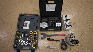
As far as tools go, there are several special service tools (SSTs) that you'll need to complete the job. I cannot stress enough how important these SSTs are, and how much easier they made this job. If you're tackling this yourself, buy all of these tools. They will double the cost of the job, but it's still less than half of having Toyota do it, and you have the tools for next time.
- OTC 6673 Universal Belt Tension Gauge
- Lisle 58430 Shaft Type Seal Puller
- Schley Products SP 64400 Harmonic Damper Pulley Holding Tool
- OTC 4518 Stinger 5-ton Bar-Type Puller/Bearing Separator Set
- (2) M8 Metric Bolts with a 1.25 Pitch, 100mm long with 4 washers - these are the bolts we used in conjunction with the OTC 4518 puller or other puller you have to remove the crankshaft pulley.
- PRIVATE BRAND TOOLS PBT70960 Crankshaft and Camshaft Seal Tool Kit Update 2022: I don't actually like to use this tool kit anymore as I've found that it bulges the seals, causing them to rip. Rather, I like to use a softer material - a small piece of wood or a brass drift - to tap evenly around the crankshaft and camshaft seals, slowly seating them into position.
- Lisle 24680 Spill-Free Funnel
- Performance Tool W89208 Cam Pulley Holder
Of course, these tools were in addition to a standard set of tools that you'd need for this job - short and deep sockets, extensions, larger torque wrenches, oil, grease, etc. Here was a list of the additional tools we used:
- 10mm, 12mm, 14mm, 17mm, and 19mm sockets - both short and deep. This is a great set, but not cheap.
- 10mm, 12mm, and 14mm wrenches. This is a good set.
- 3-, 6-, ad 9-inch socket extensions
- 10-inch socket wobble extension
- A set of socket adapters (from 1/4"-to-3/8", and from 1/2"-to-3/8")
- 90º needle nose pliers (for hose clamps)
- Two, 2-foot breaker bars
- A set of picks
- Shop towels
- 1/4-Inch Drive Torque Wrench (20-200 in-lbs)
- 1/2-Inch Drive Torque wrench capable of 250 ft-lbs
- A box of ziplock bags to hold bolts that have been removed.
- A pad of post-it notes to label said bags.
- 5 gallon container to catch coolant (bucket with trash bag liner)
- 5 qt container to catch transmission fluid
Doing the Job
With all the parts and tools gathered, it's time to get to work. Perhaps obviously, the job is mostly a bunch of removal of parts, and then a bunch of installation of those same parts - or rather, installation of replacement parts. This list of steps is just that - a list of steps (which makes it a great resource to print off and reference when you're doing the job). If you're curious about what a step looks like, I suggest watching the video linked above.
- Remove any skid plates. Note: If you have an aftermarket bumper, you may also need to remove it to gain access to the grill and radiator.
- Disconnect negative lead from the battery.
Remove the radiator
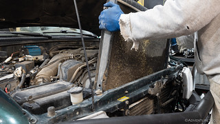
- Drain coolant out of the radiator into a 5 gallon bucket by opening valve at passenger-bottom of the radiator, and then remove the radiator cap to speed up drainage.


- Remove the front grill by releasing each of the tabs that hold it to the body, using a long flat screwdriver.
- Remove the upper radiator hose by removing the hose clamps, and then remove the hose from the radiator first, then the engine.
- Remove the lower radiator shroud by removing a metal clip on each side, and then pull the lower shroud out of the way.

- Loosen the upper radiator shroud by removing 4, 10mm bolts holding it in place (2 on top, 2 on bottom). Remove shroud.
- If applicable (automatic transmission vehicles only)
- Place a catch basin for ATF under the radiator
- remove transmission cooler lines from the bottom of the radiator.
- Disconnect coolant overflow tube from the radiator by removing the clip on the radiator side and sliding it off the hose barb.
- Place a catch basin for coolant under the radiator and then remove the lower radiator hose by removing the hose clamps, and then the hose from the radiator.
- Remove the 4, 12mm bolts that hold the radiator in place. You can remove these without the radiator falling out, since it is held up by tabs in the body.

- Lift the radiator up and out.
Remove the fan and fan clutch
- Using a long wrench, remove the 4, 12mm nuts that hold the fan clutch and fan to the fan pulley. To access each nut, rotate the crank pulley clockwise (the direction the engine turns). Note: if the motor turns on you as you loosen the nuts, use a pry bar to wedge two of the nuts in the opposing direction while you loosen the nuts.
- Pull the fan clutch and fan off of the fan pulley. (it should pull off easily)

Remove the drive belts and pulley's
- Loosen (don't remove) the 14mm pivot bolt and 14mm adjuster lock nut for the power steering belt (top-most passenger pulley)

- Loosen 14mm adjuster bolt (access may be easier from bottom of engine).
- Once the two bolts are loose enough, pivot the pulley in and remove the belt.
- Loosen (don't remove) the 14mm nut that holds the AC idler pulley on
- Loosen (don't remove) the 14mm tensioning bolt for the AC idler pulley.

- Once the two bolts are loose enough, remove the belt.
- Loosen (don't remove) the 14mm pivot bolt for the alternator
- Loosen (don't remove) the 12mm tensioning bolt for the alternator.

- Once the two bolts are loose enough, remove the belt.
- Remove the fan pulleys, noting their orientation.

Remove the dip stick and upper (#2) timing belt cover
- Remove the 10mm bolt attached to the alternator bracket that secures the dip stick.
- Slide the spark plug wire clips off of the timing belt cover.
- Unclip the spark plug wire clip on the passenger side of the timing belt cover.
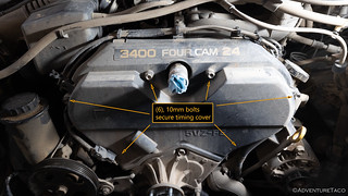
- Remove the 6, 10mm bolts holding the upper timing cover on. Four along the top, two along the bottom. Note: do not remove the electrical clip on the passenger side at this point. See step 7 below.
- Optionally (I didn't do this)
- Pull the dip stick vertically out of the oil pan, making sure that the o-ring at the bottom of the dip stick comes out as well.
- Plug the hole leading to the oil pan so that nothing drips into the engine oil while the rest of the job is ongoing.
- Remove the upper timing cover carefully to access the rear.
- Using needle nose pliers, remove the electrical connection for the cam position sensor from the timing cover.
- Disconnect the cam position sensor connector and push the two ends out of the way
Remove the adjuster bracket for power steering pump and the fan bracket
- Using a 14mm wrench, remove the nuts securing the power steering adjuster bracket.
- Remove the 14mm lock nut for the power steering tensioner, to remove the bracket.
- Remove the 14mm bolt and nut holding on the fan bracket.

- Slide off the fan bracket.
- Check the bearing of the fan bracket to ensure that it is still in good condition.
- Remove the lower radiator hose from the engine by loosening the hose clamp, and then sliding the hose off the engine. Note: with the hose, the yellow mark goes toward the engine, white mark toward the radiator.
Remove the crank pulley bolt
Note: you only ever want to rotate the crank pulley clockwise, as that's the direction it naturally rotates.
- Use the Schley Products SP 64400 Harmonic Damper Pulley Holding Tool SST and a breaker bar lodged under the driver frame rail.
- Fully seat the SST into the holes on the crank pulley.
- Rotate the crank pulley clockwise until the tool is positioned correctly for the breaker bar to be inserted and lodge under the driver frame rail.

- Insert the breaker bar into the SST and under the driver frame rail.
- Using a 19mm deep socket, remove the crank pulley bolt, making sure to apply inward pressure so as to not round off the head of the bolt.
- Remove the SST.
- Remove the crank shaft pulley using the OTC 4518 Stinger 5-ton Bar-Type Puller/Bearing Separator Set SST
- Re-insert the crank pulley bolt, screwing it in only part of the way (so the pulley will have room to slide forward as it releases).
- Using 2, 100mm M8 1.25 bolts, thread them into the two larger holes on the crank shaft pulley, leaving two washers at the head of each bolt.
- Insert the bearing puller SST between the washers+bolt heads and the crank pulley.

- Screw down on the rod in the bearing puller SST (against the crank pulley bolt) to pull the crank pulley forward.
- Remove the SST and crank pulley bolt.
- Wiggle the pulley off the remaining distance.
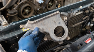
Remove the starter wire bracket and lower (#1) timing belt cover
- Remove the 2, 10mm bolts that hold on the starter wire bracket at the very bottom of the lower (#1) timing belt cover.

- Pull the bracket out of the way.
- Remove the 4, 10mm bolts that secure the #1 timing belt cover, and remove the cover.
Set the #1 cylinder to top dead center
- Look for a mark (dot) on the crank shaft timing gear pulley.
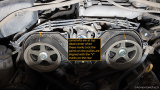
- Look for notches on each of the two cam shaft pulleys.
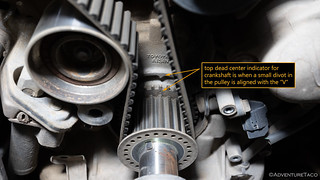
- Align the mark/dot on the timing shaft pulley with the arrow on the engine at the same time that the notches on each of the two cam shaft pulley's are aligned with the marks at the top of the timing cover by rotating the engine clockwise using the Performance Tool W89208 Cam Pulley Holder SST in a cam pulley until all three marks are aligned.
Removing the timing belt tensioner
- Loosen the 12mm front bolt of the timing belt tensioner.

- From the bottom of the truck, using a long wobble extension and 12mm socket, reach between the frame of the oil pan and wire harness to loosen the rear 12mm bolt of the timing belt tensioner.


- Remove both 12mm bolts and the timing belt tensioner.
- Optional:
- Inspect the timing belt tensioner if you are considering re-use. If there is no visible oil at the base of the pin, it is OK to reuse.
- Place the timing belt tensioner in a vise and compress the pin until you can capture the pin in a retracted state.
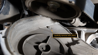
Removing the timing belt and idler pulleys
- Remove the crank pulley washer, noting the forward/rear orientation.
- Slide the timing belt off, noting the path around various pulleys.
- Remove the crank shaft timing gear(to change the seal behind it).
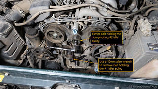
- Remove the 14mm bolt holding the non-pivoting #2 idler pulley.
- Remove the #2 idler pulley
- Use a 10mm allen wrench to remove bolt holding the #1 idler pulley.
- Remove the #1 idler pulley, making sure to also remove the washer between the pulley and the engine. Note: you will re-use this washer even when installing a new #1 idler pulley.
Remove the water inlet from the water pump, to access the thermostat
- Place a coolant catch basin under the engine to catch any coolant that will leak out.
- Remove the 3, 12mm nuts securing the water inlet.
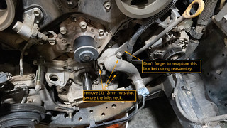
- Slide the water inlet neck off of the studs.
- Remove the thermostat. Note that the jiggle valve goes DOWN in the 6 o'clock position.

Remove the cam position sensor, cam shaft pulleys, and rear (#3) timing cover
- Remove the 10mm bolt that holds on the cam position sensor.
- Using the Performance Tool W89208 Cam Pulley Holder SST and breaker bar (and a friend), loosen the bolts holding the cam shaft pulley's on. Note: You can also use the SST and an impact wrench to do this more easily.
- Remove the 17mm camshaft pulley bolts.
- Slide the camshaft pulleys off. Note that L is Driver, R is passenger.
- Remove the small pin/key/round bar in the camshaft pulley shaft and set it aside.
- Remove the 10mm bolts holding on the rear timing cover.

- Carefully disconnect the driver side wiring loom off of the rear timing cover, by pulling the tab forward, and then the connector up.
- Remove the rear timing cover, giving us access to the cam shaft seals.
Removal and replacement of the cam shaft and crank shaft seals
- Using the Lisle 58430 Shaft Type Seal Puller SST, hook the tool between the crank shaft and seal, and then lever the seal out.

- Spread some motor oil on the new cam shaft seal, and the cam shaft. Press in the seal as far as you can with your fingers.
- Use the PRIVATE BRAND TOOLS PBT70960 Crankshaft and Camshaft Seal Tool Kit SST (determine the right spacers, etc.) to press in the new cam shaft seals. Update 2022: I've found that this tool doesn't always work well and can bulge the seals, causing them to tear as they are inserted. I have found that slowly tapping the seals in with a soft wooden or brass punch seems to work better.

I recommend not using this tool, but instead using a soft wooden or brass punch to tap the seal into position. - If the seal is not fully seated, tap it in the rest of the way.
- Repeat for the other cam shaft.
- Repeat for the crank shaft. Note: the crank shaft seal should be flush with the inside bevel, not with the face of the crank shaft lip.
Replace the water pump
- Place a coolant catch basin under the engine to catch any coolant that will leak out.
- Loosen the clamp for the oil cooler hose, and then remove the hose from (the driver side of) the water pump.
- Remove the 7, 12mm bolts that hold the water pump in place.

- Remove the water pump from the engine.
- Clean up the face of the engine where the water pump attaches, ensuring that there is a nice mating surface for the new gasket and water pump.
- Slide the new gasket over the studs for the water neck and thermostat.

- Slide the new water pump over the studs for the water neck and thermostat.
- Hand tighten all bolts, then torque all water pump bolts to 14 ft-lbs (168 in-lbs). Note: alternate nuts, bringing them up to torque spec.
- Reconnect oil cooler hose (driver side) and clamp to water pump.
Replace the thermostat and reconnect the water inlet for the water pump
- Install the new thermostat. Note that the jiggle valve goes DOWN in the 6 o'clock position.
- Slide the water inlet neck onto of the studs.
- Capture the wire bracket on the top nut.
- Hand tighten the 3, 12mm nuts securing the water inlet. Torque to 14 ft-lbs (168 in-lbs). Note: alternate nuts, bringing them up to torque spec.
Replace the rear timing cover and cam pulleys
- Place the rear timing cover back in place.
- Reattach the driver side wiring loom off of the rear timing cover.
- Reinstall the 10mm bolts that hold the rear timing cover on. Torque to 80 in-lbs.
- Replace the small pin/key in the cam pulley shafts.
- Slide the cam pulleys on, tapping the pulley on with a plastic hammer if necessary to fully seat it.
- Hand tighten the cam pully bolts, then torque to 81 ft-lbs.
- Re-align the cam shaft pulley's with the marks on the engine, if necessary, by turning them clockwise with the Performance Tool W89208 Cam Pulley Holder SST.
- Replace the cam position sensor and secure with the original 10mm bolt. Torque to 80 in-lbs.
Install the new #1 and #2 timing belt idler pulleys and timing belt
- Install the #2 idler pulley. Torque to 30 ft-lbs.
- Install the #1 idler pulley using a 10mm allen head wrench, making sure to also install the washer between the pulley and the engine. Torque to 30 ft-lbs.
- Replace the crankshaft timing gear.
- Ensure that the crank shaft gear mark is at top dead center.
- Place the timing belt on the driver side cam shaft pulley, aligning the left cam pulley with the driver side arrow and notch.
- Thread timing belt under the #2 idler pulley and over the right (passenger) cam pulley.
- Using two clamps, secure the timing belt to the cam shaft pulleys.
- Thread the timing belt over water pump pully (driver side).
- Thread the timing belt over the timing gear, making sure it is tight with the water pump pulley.
- Holding the belt tight on the timing gear, and with the timing belt tensioner loosened, push the belt onto the #1 idler pulley. Note: this requires that no tension be applied to the #1 idler pulley by the timing belt tensioner (which shouldn't be installed at this point).

- Install timing belt tensioner by
- Thread in the 12mm front bolt of the timing belt tensioner halfway - enough to hold the tensioner, but allow for installation of the rear bolt.
- From the bottom of the truck, using a long extension, swivel and 12mm socket, reach between the frame of the oil pan and wire harness to a swivel to thread in the 12mm bolt.
- Torque both timing belt tensioner bolts to 20 ft-lbs (240 in-lbs - good and tight).
- Using the Performance Tool W89208 Cam Pulley Holder SST, rotate the cam pulley's clockwise until the crank pulley gear completes two full rotations and then ensure that all marks on the crank pulley and cam pulleys are aligned top-dead-center. NOTE: the marks on the timing belt will not line up - this is OK. Align the notches in the metal pieces (pulley's and gears).
- Pull the pin on the timing belt tensioner to tension the belt.
Reinstalling everything
- Replace the timing pulley washer, in the original orientation.
- Replace the lower timing cover. Torque the bolts to 80 in-lbs.
- Replace the two bolts that hold the starter wire bracket. Torque to 80 in-lbs.
- Replace the crank shaft pulley
- Ensure that the notch in the crank shaft pulley points to the 0 (zero) when the marked tooth on the crank shaft gear is aligned with it's associated mark; and the cam shaft pulley's are aligned with their marks.
- Install the new crank shaft pulley bolt.
- Use the Schley Products SP 64400 Harmonic Damper Pulley Holding Tool SST and a breaker bar under lodged under the passenger frame rail to hold the crank shaft pulley steady. Torque the crank shaft bolt to 217 ft-lbs.
- Be sure to route the cam position sensor wire in the plastic bracket, and route the wire through the indentation in the timing cover. This ensures that it doesn't run into the timing belt.

- Replace the fan bracket by sliding it over the studs.
- Reinstall the top bolt and driver side nut; finger tighten only.
- Reinstall the power steering adjuster bracket over the passenger side fan bracket stud.
- Reinstall the passenger side nut for the fan bracket over the fan bracket stud.
- Tighten all bolts/nuts for fan bracket. (good-and-tight; no torque specs given)
- Ensure that the cam position sensor wire is routed between the upper, lower, and rear timing covers.
- Reinstall upper timing cover, ensuring that cam position sensor connector is clipped in and available as originally installed. Torque all 6, 10mm bolts to 80 in-lbs.
- Reconnect clips for spark plug wires.
- Reattach the top bracket for the oil dip stick. Torque to 71 in-lbs.
- Replace the fan pulleys. Note: The forward pulley fits with the "dished out" side to the rear of the vehicle.
- Replace fan clutch. Finger tighten the 4, 12mm nuts; then alternately torque to 105 in-lbs.
Installing belts and final fan clutch tightening

- Fit the alternator belt. Tension the belt using the OTC 6673 Universal Belt Tension Gauge SST. Tension to 120 lbs. Note: after a few minutes of use, the belt should loosen to ~100 lbs.
- Tighten the adjuster lock nut, but not fully as we'll fully tighten after running the truck for several minutes.
- Fit the AC belt. Tension the belt using the tensioning SST to 120 lbs, or 100 lbs after a few minutes of use.
- Tighten the pulley nut, but not fully as we'll fully tighten after running the truck for several minutes.
- Fit the power steering belt. Tension the belt using the tensioning SST to 120 lbs, or 100 lbs after a few minutes of use.
- Tighten the adjuster lock nut, but not fully as we'll fully tighten after running the truck for several minutes.
Reinstall the radiator
- Drop in the radiator and capture the brackets/hooks in the body to hold the radiator in place.
- Secure the 4, 12mm bolts that hold the radiator in place. Torque to 105 in-lbs.
- If applicable, slip the driver and passenger transmission cooler lines over the fittings in the radiator, and secure with hose clamps.
- Replace the lower radiator hose. First, attach the hose end with the yellow mark toward the engine; secure the white mark towards the radiator. Secure with hose clamps.
- Insert the upper radiator shroud between the fan and radiator. Secure with 10mm bolts. (tight)
- Replace the upper radiator hose. First, attach the hose end with the yellow mark toward the engine; secure the white mark towards the radiator. Secure with hose clamps.
- Replace the radiator overflow tube. Secure with hose clamp.
Refilling fluids
- Fill transmission fluid to replace any that was lost when removing the radiator.
- Ensure that the drain valve on the bottom of the radiator is closed, so fluid doesn't just leak out.
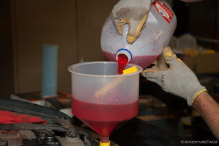
- Install Lisle 24680 Spill-Free Funnel SST to fill valve of the radiator.
- Fill the radiator with coolant concentrate, mixing 50/50 with distilled water, if necessary.
- Reconnect negative battery cable.
- Start the engine and let run for a 2-10 minutes, until the operating temperature reaches 180ºF and the thermostat opens.
- Monitor fluid levels - transmission and coolant; fill as necessary.
- Check belt tension; re-tension to 100 lbs each as necessary by loosening pivot bolt, and then tightening tensioners.
- Drive the truck for ~10 miles and monitor temperatures
- Transmission fluid - 158°F - 176°F
- Coolant - 180°F - 190°F
- Check fluid levels - transmission and coolant; fill as necessary.
- Check belt tension; re-tension to 100 lbs each as necessary by loosening pivot bolt, and then tightening tensioners.
- Proper torque specs
- Alternator lock nut - 25 ft-lbs
- Alternator pivot bolt - 38 ft-lbs
- AC pulley nut - 29 ft-lbs
- Power steering pivot bolt - 32 ft-lbs
- Lock nut for adjuster - 32 ft-lbs
- Proper torque specs
You are done! Congratulations.
Crazy (as in great ) complete, detailed and well written!
Thanks George, I hope it was helpful for you!
thanks, is 1997 t-100 3.4 auto an interference engine?
No, the 3.4 (5VZFE) is not. It's non-interference.
thank you
Amazing write up. I need to do this job soon and this will definitely help. Thank you!
Absolutely - glad you found it John, and by all means ask if you have any questions!
Great writeup! How long did the service take you?
Thanks Benjamin! I wrote up the story of doing this (with a buddy who did his truck at the same time), over here: Yes We're Crazy Shop Day: Replacing the Timing Belt (and more) in Two Trucks At the Same Time. It was our first time doing the job, and it took us about 14 hours, since we had to overcome a few obstacles along the way. Lots of photos in that post, so check it out! ?
How far does the crank stick out of the block when its all the way exposed?
Hi Tony, I don't recall exactly how far the crank sticks out of the block. Three to four inches perhaps? It's been a few years now, so the best I have is this photo.
Thanks for the reply. I watched timmy the toolman's video again (for like the 17th time). I was able to get a pretty good reference when he pulled the seal.
Excellent write-up! Don McGill Toyota in Houston wanted to charge me $1600. After buying the complete list of tools and parts I still saved ~$800.
Thanks for making it so easy.
Awesome! Similar pricing for me, and next time the job will be even "cheaper" since I'll have to tools already. ?
Thanks for all the great info, I live in the eastern Sierra so it’s been fun to look at some of your recent Death Valley posts as well, pretty neat country eh. Any way just recently completed a timing belt job as you so eloquently laid out here and well I was at it put in a new radiator and hoses just for preventative maintenance. After this I’ve been running a fair bit hotter as per my ultra gauge. Used to be 189-194 average and hottest I’d ever seen it maybe 202, now I’m running 199-206 average and have seen 213. According to the internet I was convinced it was because I installed the jiggle valve at 12 o’clock not 6 so today I cracked it open and flipped it… same temperature to the degree while driving. Wondering if you monitor your temperature and what your truck averages? Radiator and thermostat are OEM. Any ideas would be greatly appreciated! Thanks
Sam
Hi Sam, Sorry for the slower reply - was out in Death Valley again for the last week; it's become my second home for the winter (not that I'm complaining!) As far as temps go - I do monitor mine and they stay in the 188-190 range - right around what it sounds like you were seeing prior to the timing belt job. I too was going to suggest the jiggle valve as a possible solution, but it seems that you already checked that. The only other thing I can think of is that the new radiator just isn't as efficient as the old one. Sounds like you put an OEM Toyota replacement in though, so I wouldn't expect that to cause any issue either (but that would have been my next guess).
Just throwing a few ideas out there - you've verified that the fluid levels are all full? Mixure of coolant/water is correct? I suppose you could have also gotten a bum thermostat - that might be the next thing I'd check after verifying the fluids. I'd love to hear what steps you take, and if you are able to get to the bottom of the increased temps, since I'm about to do the timing belt job again...
freaking amazing set of instructions - my kiddo got the job done!
Thanks so much! Glad the instructions were helpful! Anything in the process that could be improved, or places that your kiddo ran into issues? I'm always happy to update with the experience of others! ?
A few tips that helped me in the job yesterday:
It is possible to remove the crank shaft bolt with an impact! Made getting it off wicked easy! We tried rigging up all sorts of things with double breaker bars and all and the impact zipped it off in moments. Of course we will have rig up some solution in order to tighten it back down, but an impact does not spin the whole crank, at least it didn't on mine.
Don't install the tensioner before loading the new timing belt! Timmy's video shows this in the wrong order.
Also, an alternative way to thread the timing belt: Start at the bottom on the crank shaft, up to the right (facing the vehicle and around the Driver side pulley. Then over to the Passenger side pulley and lastly down around the belt tensioner. Note that the passenger side cam will pull back just slightly when tensioned. Made the job so much easier!
Hey Luke, Glad the guide helped out. The impact can definitely work well on the crank bolt in a lot of cases - that's how I do it as well. Not everyone has an impact though, so showing the breaker bar method is a good option for them!
I'm right there with you on the tensioner as well. I always put it on after the belt (as noted in the guide above), and didn't realize Timmy did it before putting the belt on.
Thanks for posting up your tips - always good for others to hear what works and what doesn't on a job like this!
I became aware of the AdventureTaco DIY How-To series via a forum that I frequent. All comments were positive and I needed to replace my timing belt, on my 03 Tacoma. The AdventureTaco website is easy to navigate. The details provided were awesome; parts/tool list with numbers, accurate step-by-step, clear pics, and torque values for reassemble.
Knocked it out in a day with no issues. The effort put into this How-To is much appreciated.
Thanks Rob, super glad to hear everything worked out for you and the how-to was helpful! If you have a chance, I'd love a positive review on Google and/or facebook, it turns out they help with search results lot more than I originally realized they do! (Totally up to you though, mostly I'm just happy to help.)
Unreal how detailed this is! If only shop manuals were as clear. Great photos ! Thanks for your hard work compiling this.
Awesome, glad it could be of help Chris!
Hey, thanks for this tutorial, It has been very helpful in getting this done on a 90 series Land Cruiser! I just wanted to correct one torque spec. The no 1 idler pulley (tensioner pulley) has torque spec of 26 ft lbs (35nm) according to FSM. Maybe not a huge difference. But since that bolt goes into aluminum housing, thats probably the reason for the slightly lower spec.
Glad the guide was helpful for ya on your 90 series! Interesting to hear the torque spec on that #1 idler was different for you - in my 2000 Tacoma FSM (and in the 2003 as well) it's clearly labeled as 30 ft-lbs. I wonder if Toyota used a different spec on the LC for a reason.
5VZFE torque specs from 2000 Tacoma FSM. (click to enlarge)
Thank you very much for the thorough instructions and great photos. I'll be doing this on my '04 Tacoma soon. Will download it into my laptop for onsite reference as needed.
Awesome David, glad you found it useful and good luck on your '04 timing belt job. I remember the first time I did it I was a little nervous, but it turned out to be reasonably straight forward with the right parts kit and taking my time. Hopefully it'll be the same for you!
Great document! I had a mf'r getting the hidden tensioner bolt in until using a 3" x 1/4" extension.
Glad to hear you got it and that the guide was useful!
Great set of instructions. I got everything apart and am ready to go back together.
However, when I was loosening the crank shaft bolt with the special 2-pin tool, the donut (ie, the harmonic balancer?) came loose, not the bolt. I used the starter method to get the bolt loose. Worked nicely.
I think I need a new balancer assembly as a result. Given that this happened, I'm nervous about using the tool to torque the bolt back in place.
Thoughts?
Hey Art, the balancer should be keyed to the crank shaft, so I'm not sure how it would "come loose" unless the metal key is missing. And, I don't know of any other way to torque it to 217 ft-lbs without using the special tool. Have you verified that the key is still there, and that the notch in the harmonic balancer still fits over it correctly (and isn't wallowed out)?
Haven't done it yet, but this is the best tool in the box.
Thank You
More comments after the job is done.
Awesome, thanks Frank! By all means, reach out if you have any questions, and good luck!
I was moving too fast with a buddy and cut the timing belt off before setting it to TDC.
We then manually moved the 2 cams and crank so the timing marks matched the timing indicators (V's)
Then the project sat for 2 months.
I just put everything back together (with marks and arrows all aligned) and it turns over, but doesn't start.
My guess is that the cams rotate multiple times for each crank rotation, and one or both of my cams are out of position.
Is my assumption correct, and where would you start to fix this?
Hey Chase, Moving too fast is something we all do, so no worries there. Good news though - as long as the alignment marks are TDC (top dead center), everything is aligned correctly. You do not need to worry that the cams need to be "rotated to a different TDC," because there is all TDCs are equivalent. I've most definitely turned them all independently before and never run into an issue.
Here's a bit more as far as getting everything aligned goes: without the belt installed, the camshafts and crankshaft are independent. Turn whatever you need to independently to reach TDC on all three shafts - but ensure that you're always turning them clockwise when facing the engine from the front. When turning the cams, they will want to flip into different positions as the cam lobes overcome valve spring tension but that's totally normal. As you get close to lining up the timing marks, you will find a sweet spot just before the cams want to flip over.
Note: It doesn't sound like you are, but if you're encountering a lot of pressure while trying to turn one of the cams you're going to want to pull the cover and see what's going on. It shouldn't take a whole lot of pressure to turn them, but it is a lot more than the crankshaft which spins freely.
The more common "TDC alignment" issue that I see is that people think that they've got the timing belt installed when everything is aligned TDC, when in reality the belt is off by a tooth (or even two) on the crankshaft. This is because all - and I mean all - of the slack in the timing belt has to be between the passenger side of the crankshaft and the passenger side contact point of the belt with the passenger side camshaft. There can be absolutely no slack between TDC of the passenger side camshaft and the driver side contact with the crankshaft.
This turns out to be rather difficult to achieve - at least for me - and often requires very minor finessing of TDC for the camshafts, sometimes rotating them by fractions of a degree (always clockwise) in order to get the correct number of "timing belt teeth" between the cams and crankshaft.
The "good news" is that it's reasonably simple to find out if you've done it wrong (or right!). Once you have the timing belt and tensioners installed with everything in what you believe to be TDC, turn the crankshaft clockwise exactly two full revolutions, so that the crank shaft gear mark is at top dead center. At this point, the two camshaft marks should also be TDC. If they are not, then you don't have the belt on quite right (off by a tooth or two), and it'll be hard/impossible for the truck to start.
NOTE: Marks on the timing belt that were previously aligned with the TDC marks on the pulleys/gear will not line up after two clockwise rotations - this is OK.
The other thing to check is that you have the cam and crank sensors plugged in and that none of the wires were broken in the process of replacing the timing belt.
Hope that helps! Let me know what you find, or if you have other questions!
Did you end up figuring out what was wrong, I am having the same issue.
Are you sure you're getting fuel and spark? As long as you have the TDC marks lined up correctly, the problem is unlikely with the timing belt itself.
Yup, it was just as turbodb said. I took the timing belt off, realigned everything, prayed to the Lord, put it back together, and she started beautifully!
Awesome!
So you line the top 2 gears to the notch and the bottom to the notch and it’s in time? And you put the belt and everything else on?
That's correct. Please see the recent question and answer from Chase here, where I go into a lot more detail.
Wanted to say Thank You for this excellent write up. I used it as my primary guidance for my timing belt kit install. Your simple instructions + data really made it easier.
Awesome, glad they were useful for you Jason! 👍
Very helpful info thank you! This took some time to put together!
As a seasoned tech, I just needed a few pointers and torque settings. One thing I wished was highlighted more for my speed reading was the thermostat in the 6 o’clock position. Can’t think of another application where that was important! I also found it easier to remove the AC compressor and bracket from above, to get to the tensioner bolts.
Cheers,
Connor,
Atlanta GA
Glad it helped Connor. I updated the notes on the themostat to be red rather than gray like the rest of the notes in the guide. Hopefully that helps folks who are skimming through in the future.
Removing the A/C compressor is an interesting tweak. I'll take a look at that next time I do the job and may add it to the guide if it works out well. 👍
I'm glad to hear the AC compressor is easy to get out from above when you've got half the engine bay taken apart - mine's seized and I was planning on doing it the same weekend as the timing belt. Hoping I don't discover it blasted a ton of shrapnel into the cooling side of the HVAC system when it went.
Sets a lot of my nerves about this job at ease.
Good luck!
Hey - just wanted to add another voice to all the other ones thanking you for this write-up - it really helped me with the belt on my '04. Looking forward to 90K more miles of smooth sailing.
You're welcome, glad it was useful! 👍
Thank you for the detail guide and all the information you've posted about your journey with the Tacoma. I recently picked up an 02' Tacoma with 157k miles, and although the timing belt was replaced at 93k, that was over 17 years ago. I've gathered the parts, need to get a few more special tools in then I"m ready to tackle this job.
Cheers,
John
Sure thing John, glad you found it helpful!
Best write up ever! The thermostat jiggle valve is a funny topic. Automakers and thermostat makers for nearly a century have said 12 o'clock for the jiggly, to allow trapped hot air out. But Mr. Toyoda in the Toyota Factory Service Manual says the 5VZ is 6 o'clock, and the engine should run cooler because the hot fluid sneaks through, rises to the wax, and opens the thermostat sooner. At 12 o'clock it would logically let trapped air out, but Toyota wants it at 6 to heat the wax and open baby open for a cooler engine!
Glad you liked the write-up Scotty, always nice to get feedback like that! 👍
Finished up my timing belt job. This guide and the videos were very helpful. I second not installing the tensioner until the timing belt is on. Unfortunately I relied too much on the video and not this guide.
One thing I know I did wrong is I installed the Jiggle Valve at 12 0'clock instead of 6 O'clock. I watched several videos and kept seeing different advice, and in my service manual it said 12 O'clock......BUT.....that was for the 4 cylinder engine. Doh!
Should I go back in and flip the thermostat?
Thanks again!
John
Hey John, glad the guide was helpful! Do you have a good way to keep an eye on engine temps? If you do, have a look to see if you're hovering around 189-191 with the jiggle valve at 12 o'clock; if you're not - and you're significantly higher than that - I'd look at going back in to flip it around to 6 o'clock.
Good luck!
I went back in this evening and flipped it around, so we should be all good now.
Cheers,
John
After I recover from this job, I'm going to tackle rebuilding the suspension. It's not the same wrenching at 55 as it was at 25. I look forward to looking through whatever other helpful guides you have posted on your journey with Adventure Taco. I named my truck Taco, and my 3 year old granddaughter loves her and always asks where Taco is. Now I can never get rid of it. :¯\_(ツ)_/¯
Cheer,
John
Awesome, glad to hear you got it flipped around; nice not having to worry about it!
As for getting rid of the Taco ... I mean, why would you want to get rid of it, regardless? 😉
Good luck with future work on the Taco, and feel free to shout if you have questions!
Thank you for these detailed instructions. My son is going to tackle this on his first car and I just had a question about whether there are any extra steps with it being a manual transmission? Would appreciate any insight you would have. TIA
Hi DS, no extra steps with the MT. I’ve got an MT as well! Good luck, it’s a time consuming project, but going slowly it’s not that bad. 👍
haven trouble getting my timming belt on. can't get it over the tensioner
Hey Tyler, the tensioner shouldn't be installed when you're installing the timing belt; if it is installed, you'll have a really hard time getting the belt on (as you're experiencing). See this part of the guide.
The following step is to install the tensioner, which - even when the pin is installed will push the tensioner pully a bit - then tightens everything up.
If you can't get the belt on when the tensioner is not installed, my suggestion would be to try to slide it onto the crank pulley and through the tensioner pulley at the same time, being careful to not "lose" the engagement at the cam pulleys, since you need to be sure those stay tight/aligned.
Hello. What an awesome set of instructions. The tensioner back bolt....holy cow. l have seen other threads/videos suggesting the wobbly. You're the first to suggest access from underneath. .....others have not gone into that detail. Would you suggest 1/4" drive and attachements? I can't tell from your picture it that's 3/8" ratchet etc. I do know ya can't get to that bolt from above, with a wobbly......dang A/C bracket. 340,000 on my truck....looks like the belt etc has been done recently....yet the tensioner looks like it has 340,000 miles on it. I think I know what it hasn't been changed
Hey Jim, glad you found the instructions and that they've been useful! For reaching up there from below - I used a 3/8, but I always have my 1/4 stuff around just in case. Use whichever works best for you in the moment.
And 340 on the truck is pretty awesome. I'm going to pass through 300 here in a couple of months, which is amazing given how I beat on my truck. Hopefully it's got another 200K left in it, since it'd be rad to hit the half million mark some day.
Thanks. It has been a great truck. 1999. Not the best payload capacity......but very dependable and durable. Man, I'm seeing several negative stories about getting that bolt back in.....seems to be the most common speedbump in this job. I think I know why I hear mechanics say in their videos....."customer didn't want to replace the tensioner." Thank you for your attention.
Yeah, still not "easy" to get that bolt from the bottom, but with some patience, totally doable. And the feeling when the threads catch is fantastic! 👍
What about the timing cover seals?
Hey John, The timing cover "seals" aren't really seals at all - or at least, they aren't sealing much more than large debris getting under the cover - and there's no real reason to replace them from a functional/engine maintenance perspective. Are you running into an issue with yours that would benefit from replacement?
Yeah im currently overhauling the entire engine , just finishing the water pump timing kit and whoever owned this previously used gasket sealant on the timing cover and it all fell off , i did pick up the ASIN timing cover seal kit but theres not much info out there on where the seals go , even the frm has a somewhat difficult to read image of them but no reap text on the matter - thanks for the reply!
The previous owner really abused this sr5 so the entire engine i rebuilt and cleaned as it was caked in dirt and oil n such so i wanna replace everything including the seals on the cover correctly
Gotcha, cleaning up from a previous owner makes a lot of sense. Good luck!
Did a quick search myself for that kit to see if I could find instructions, but no luck. I guess I'd hope that the lengths of the rubber were the correct lengths to match up to the diagram of where they go.
Should have taken a before photo, engine was completely neglected, overhauling it all myself , been a fun ride and cant wait to start it up
Dude. Thank you. Just finished up and she’s running good.
Awesome, glad to hear! 👍
Hey Sir. Your site is so helpful.
Discovered a WP leak so I just ordered the kit from RA. I don't plan on changing out the Cam or crank seals just yet. Do I still need the SST tool for the Cams or is there a cheaper alternative?
Also for the crank bolt, I'm pretty sure my Impact will easily remove it but is there a trick to reinstall to "torque" without the SST for the harmonic balancer?
Sorry trying to save a few bucks.
Hey Jas, glad you found the site and hope you get the pump replaced with little trouble. As far as those SSTs go - there's no real trick to either of them; they are levers that hold the pulleys still while you torque the bolts, so if you can make your own levers, those should work just as well. It's really just a matter of time/money from that perspective, since making them will involve some trial and error to get the "pins" on the levers welded into the right place.
In general, I've found that purchasing both of those is worth it from a time perspective, but they really are just pieces of metal with no moving parts, so they could be welded up if you've got scrap laying around.
Just finished doing this job last night and wanted to send a huge thank you for your effort to write up this post! It's helped a bunch of us!
Evan
Awesome, thanks for letting me know Evan, and glad the guide was helpful to you! If you have a chance, I'd love a positive recommendation on Facebook. I've never really paid attention to those before, but I hear they help quite a bit!
Wanted to add to the chorus thanking you for this detailed write-up- in particular, the picture with the ELECTRICAL TAPE on the tool setup for the tensioner bolt was key for me. I'd been struggling with that damn wobble socket op next to the oil pan for 2 days!
Yay! Glad to be of help!
Both you an Timmy the Toolman remove the radiator, but the FSM never mentions it. Is there a reason you pulled it? Just more space?
Yep, just more space. You can do the job with the radiator in (and I have), but then you get to worry about mashing the fins as you wrestle with various other high-torque parts of the job, etc. I always feel like pulling it is so easy - just 4 bolts - that I might as well do it in order to give myself some peace of mind.
Cool. I've pulled the radiator before, and you can get to the 4 bolts with a wobble without removing the grill. I also want to point out that in 2004 Toyota went to the "Super long life" premixed coolant. The parts guy at my local dealership said it's the same stuff as the concentrate, but the internet tells me otherwise. Dunno if it's worth noting in your write up. This is easily the most comprehensive write-up I've seen for this. Thank you so much!
I think that Super Long Life may be better (longer service life), but I've always just kept using the concentrate and distilled water, because it's worked so well for me over the decades. It'd be nice if they sold the super long life concentrate in the US market, but alas, as with many "best of" Toyota things, we don't get it.