")
I've discussed the trade-offs between disposable and rebuildable shocks in the past as I've replaced spherical bearings in my ADS coilovers, but I've never walked through the process of actually rebuilding the internals of a smooth body shock before. But, now that my shocks have absorbed some ~80K miles, it's time to rebuild and revalve them - so they can provide the same great service in the years to come, as they carry me and my stuff over thousands of miles of dirt roads.
Related Guides
Every shock manufacturer makes their shocks a little differently. I originally learned how to do this work by watching the rebuild of a King shock, and applied it to my own ADS. However, I recognize that it's always nice to have a guide that matches your exact setup, so I've created guides for each manufacturer that I've encountered.
")
Parts and Supplies
In order to rebuild your shocks, you'll need several replacement parts and supplies. I'm sure there are numerous places to get these, but I recommend Tim @TMFF at 303 Shock Services. Some of this you can find on his site, but I certainly recommend giving him a call with any questions you have. And - if it seems too intimidating to tackle this yourself, you can even send him your shocks and he'll do the rebuild (and/or revalve) for you.
For each shock you are going to rebuild, you will need the following:
- To replace the bearings in one shock (all of these parts are available in a kit):
- Two (2) spherical bearings. I recommend going with FK brand bearings in -F1 tightness (extra tight), and either the FKS10T-F1 (hardened steel) or FKSSX10T-F1 (stainless steel) versions.
- Four (4) C-clips
- Misalignment spacers
- To replace the seals - purchase a kit for your shock brand. Note that if you have clickers or bypasses, or no resis, you may need different seal kits. Contact Tim, or your manufacturer.
- If you are revalving your shocks at the same time, you'll need the appropriate shim stack. Contact Tim to determine (for a fee) the right set of shims for your needs.
- Shock Oil - you'll need approximately 1 gallon for two (2) shocks w/resis.

Tools
One of the reasons to pay someone like Tim to do this work for you is that many of the tools to do the job are specialty tools, and unlike other tools that can be used on other jobs, these are primarily used for rebuilding shocks, so it will take a while to amortize the cost.
- Specialty tools
- Branick 7600 spring compressor - used to compress the springs on coilovers, for removal.
- 20 ton shop press (sometimes Harbor Freight is cheaper) - used to press spherical bearings in/out of the shock eye(s), though you can also use a sturdy vise for this task.
- Shock / Reservoir Housing Wrench. Note: these are manufacturer specific.
- Nitrogen Refill Kit, consisting of:
- Nitrogen Regulator - 0-400 PSI
- Nitrogen Fill Gauge - Lossless valve, and 0-300 PSI
- Hose - to connect regulator and fill gauge
- Nitrogen Tank - It's best to pick this up pre-filled at your local Airgas-style (or welding) supplier, but you can buy a 20 cubic-foot empty tank as well and get it filled.
- A case (amazon) (Harbor Freight) to store all the kit pieces in (optional).
- Reservoir Piston Positioning Tool. Note: you can also (generally) use a 1/4" x 20 threaded rod in place of a special tool.
- 18" Locking Surgical Clamps - or something long and narrow that can hole paper towels for cleaning shock and reservoir housings.
- Standard tools
- Misc sockets (I recommend this kit) - for removal of the shocks from the vehicle.
- Misc wrenches (I recommend this kit) - for removal of the shocks from the vehicle.
- A set of Allen key wrenches.
- Internal snap ring pliers - to remove retainers for the spherical bearings.
- Pick set - for seal removal.
- A sturdy vise - to hold shock as you're working on it.
- Aluminum vise jaw protectors - to protect the shock as it's held in the vise. Note that you could use wooden protectors as well, if you have those available.
- 5 gallon bucket - to catch shock oil as it drains.
- Schrader valve core tool
- A small bike pump with guage - to assist with removal of the shock shaft if it's difficult to remove.
- Rubber mallet
- Shop towels
- Work gloves
- A short length (~3") of 1.5" PVC pipe, cut in half.
- A small amount of blue loctite.
- A small, fine grit Emory stone - for polishing the shock shaft if there are imperfections.
- A little bit of Red-n-Tacky Grease - for greasing the new spherical bearings as they are installed.
Terminology
Thanks to King Shocks for making this nifty diagram that labels all the parts of the types of shocks that this guide/tutorial covers rebuilding. The guide doesn't touch on all these parts, but if it references a part you are unfamiliar with, you can likely find it here.

1 - Top Cap
2 - Top Cap O-Ring
3 - Secondary Nuts
4 - Secondary Nut O-Ring
5 - Shock Cylinder
6 - Coil Adjustment Nut
7 - Coil Spring
8 - Coil Slider
9 - Coil Plate
10 - Piston Retaining Nut
11 - Piston Retaining Washer
12 - Valve Shims
13 - Piston Wear band
14 - Piston
15 - Base Washer
16 - Top Out Washer
17 - Shaft Spacer
18 - Shaft Guide / DU Bushing
19 - Seal Cap
20 - Shaft O-Ring
21 - Main Seal
22 - Main Seal Retainer
23 - Seal Cap O-Ring
24 - Shock Cylinder C-Clip
25 - Wiper Cap O-Ring
26 - Wiper Cap
27 - Wiper Seal
28 - Set Screw
29 - Shock Shaft
30 - Rod End
31 - Coil Adjustment Pinch Bolt
32 - Piggyback Mounting Sleeve
33 - Reservoir C-Clip
34 - Piggyback Adaptor O-Ring
35 - Piggyback Reservoir Oil End Cap
36 - Reservoir O-Rings
37 - Reservoir Cylinder
38 - Reservoir Piston Wear Band
39 - Reservoir Piston
40 - Remote Reservoir Air End Cap
41 - Schrader Valve
42 - Piggyback Mounting Plate Bolts
43 - Piggyback Mounting Plate
44 - Piggyback Reservoir End Cap Bolts
45 - Spacer
46 - Bearing C-Clips
47 - Spherical bearing
48 - Piggyback Mounting Sleeve O-Rings
49 - Piston O-Ring
50 - Main Seal C-Clip 51 - Wiper Seal C-Clip
52 - Wiper Seal Retainer
53 - Wiper Seal
54 - Wiper O-Ring
55 - end cap Bolts
56 - Remote Reservoir Hose
57 - Remote Reservoir Oil End Cap
58 - Remote Reservoir End Cap O-Ring
59 - Schrader Valve Cap O-Ring
60 - Schrader Valve Cap
61 - Piston Bleed Screw
62 - Seal Cap Bleed Screw
63 - Bypass Valve
64 - Bypass Spring
65 - Bypass Valve Stop
66 - Bypass Valve Stop Set Screw
67 - Bypass Valve Stop O-Ring
68 - Bypass Adjusting Nut O-Ring
69 - Bypass Adjusting Nut
70 - Bypass Adjusting Screw
71 - Bypass Adjusting Jam Nut
Doing the Job
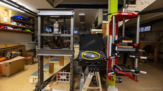
There are really three parts to a shock rebuild - removal/installation of the shocks, work on the external components (bearings, etc.), and work on the internals (seals, shims). I'll only cover work on the external and internal components here; since removal/installation of the shocks is shock-specific and - I assume - general knowledge. As such, this guide starts when the shock(s) you plan to rebuild are sitting on the bench.
Additionally, this process is the same for shocks most shocks with reservoirs, whether they be, though each may have more/fewer seals to replace:
- remote or piggyback reservoirs
- have (or not) clickers
- have (or not) bypasses
Lastly, some steps are specific to coilover (generally front) shocks, and can be skipped for non-coilover applications.
Removing the Coil Spring (coilovers only, obviously)
Compressing coils to remove them from coilovers can be a dangerously touchy operation. A wall-mounted spring compressor is clearly the safest tool for this job, but doesn't come cheap. Another option - that is safer than using one of the spring compressors you can rent at a parts store - is to take your coilovers to a shop and pay them a few bucks to remove/install the coils on their wall-mounted unit. Shouldn't be too expensive, really.
- Place the coilover in the spring compressor with the bottom of the shock pointed up, and the end with the reservoir hose pointed down.

Orienting the shock in this fashion will allow easier removal of the retaining ring. - Use the spring compressor to compress the spring until the spring is not exerting any pressure on the lower coil plate, and the lower coil plate can be slid down off of the rod end revealing the retaining ring. Note: you will need to push the shock up from the bottom in order to expose the retaining ring.

- Use a pick to remove the wire retaining ring that holds the two larger semi-circular retaining rings to the rod end.

- Remove the two larger semi-circular retaining rings to the rod end.
- Carefully release the tension on the spring compressor, and remove the entire coilover assembly to a workbench.

Removing Coilover Top Pate to Access Spherical Bearings
- Locate the single, 1/2", 12-point bolt that secures the top plate to the shock body via the spherical bearing.

- Use a 1/2", 12-point socket and an impact wrench to remove the bolt from the top plate.

Removing the Spherical Bearings
- Remove the misalignment spacers from the spherical bearings. Note: These may be hard to remove due to corrosion, but do this carefully so you can reuse the misalignment spacers.
- Clean out as much grease/grime from the rod end as possible.
- Use a pair of internal snap ring pliers to compress, and then remove, the snap rings from each side of the spherical bearing. Note: technically you only need to remove one snap ring, but the process of pressing out the spherical bearing is easier if you remove them both.

- Using a shop press and two sockets - one large enough to capture the spherical bearing as it is pressed out, and one that presses on the outer race of the spherical bearing to push it out - carefully press the spherical bearing out of the rod end.

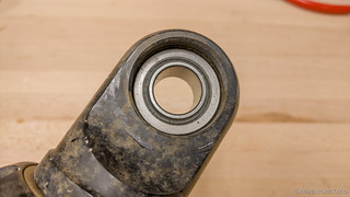
- Inspect the rod end for excessive wear, and use a bit of sandpaper to clean up the surface if necessary. Note: the rod end is often aluminum and so quite soft compared to the steel bearings. If excessive wear is present, or if the bearing does not fit snugly, replace the rod end.
Installing New Spherical Bearings
It is recommended - though not strictly necessary - to use new snap rings when you install new spherical bearings.
- Use a pick to clean out the snap ring grooves in the rod end.
- Use the internal snap ring pliers to compress, and then insert, a new snap ring into one of the snap ring grooves. Note: The new spherical bearing will be pressed in until it bottoms out on this snap ring.
- Spread a bit of grease on the outside of the spherical bearing and on the inside of the race in the rod end.
- Using a shop press and two sockets - one large enough to support the rod end, and the other that presses on the outer race of the spherical bearing, slowly press the new spherical bearing into the rod end until it bottoms out on the snap ring.Note 1: It is extremely important that the bearing go in square, and smoothly. If it does not go in square, it will damage the aluminum rod end race, and you'll need to buy a new rod end.Note 2: Once the bearing bottoms out on the snap ring, stop. Do not over press.
Once the bearing is seated, you will be able to see the groove for the second snap ring. - Use the internal snap ring pliers to compress, and then insert, a new snap ring into second of the snap ring grooves, capturing the spherical bearing.
Depressurizing and Removing the End Cap from the Reservoir
- Remove (unscrew) the caps - one outer, and then the actual valve cap - on the Schrader valve at the end of the reservoir.
- Point the reservoir away from you, and use a valve core tool to release the pressure from the reservoir. Note: if there is no pressure released, then the shock has lost pressure. The most common cause of this is a valve core that has rattled loose.
- Use the valve core tool to remove the valve core. This valve core can be reused if it is in good shape.

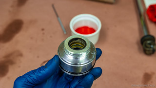
With the valve core removed, the gas chamber of the reservoir can now breath freely. - Use the Shock / Reservoir Housing Wrench to loosen, and remove the reservoir end cap by completely unscrewing it from the reservoir. Note: There are two seals on the end cap, and you will need to pull/wiggle it out once it stops threading out.
Removing the end cap. 
Note the two seals. - Clean any residual dirt out of the reservoir with a paper towel.
- Inspect the inside walls of the reservoir for scaring/marks/oil. A small amount of oil is normal, a larger amount may indicate a problem. If the inside walls are in reasonable condition, clean out any oil with a paper towel.
- Inspect the end cap for scaring/marks. If it is in reasonable condition, set it aside, otherwise consider purchasing a new end cap.
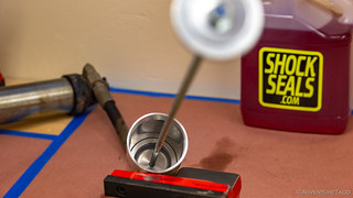
Measure the Distance to the Internal Floating Piston in the Reservoir
These steps are necessary in order to establish the amount of oil that will be added to the shock during the rebuild process.
- If your reservoirs have clickers, turn them until they are fully opened up, so oil can flow freely.
- Fully extend the main piston on the shock.
- Use a tape measure to measure the distance from the outer edge of the reservoir to the deepest point (center) of the piston.

- Record the position for later use: _____________ Note: there should really only be 1.5-2.5 inches of oil in the reservoir, certainly less than 50% of the reservoir length.
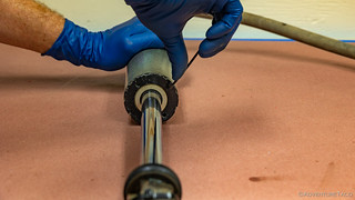
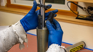
Removing the End Cap from the Shock
- Locate the set screw(s) on the bottom of the end cap, and clean out any grit/dirt/grime so that the appropriately sized Allen wrench can be inserted into the set screw. Note: if you break or strip this set screw, you have to drill it out, which is difficult with the shock shaft in the way.
- Carefully break the set screw loose, and then loosen -and remove it.
The set screw locks the end cap against the internal shaft retainer, and while it only needs to be loosened enough to allow the two components to spin independently, I find it easier to remove and set aside. - Use the Shock / Reservoir Housing Wrench to loosen the end cap, then unscrew it completely and slide it down the shock shaft. Note: There may be a bit of corrosion at the end cap. If you have difficulty threading it off the end of the shock, one or more of the following may help to loosen it:
- penetrating oil,
- a quick snap with a dead blow hammer on the end of the wrench,
- adding a bit of pressure (50-100psi) back to the shock in order to loosen it.

The end cap is captured on the shock shaft until the shaft is removed.
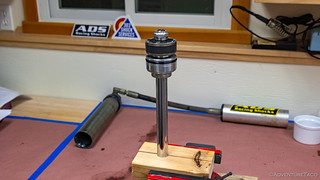
Removing the Internal Shaft Retainer and Shock Shaft
This part of the procedure results in removal of the entire shock shaft from the housing, which means that the oil in the shock is also released. Be prepared, and have a catch container on hand to capture the used oil.
- Position the shock vertically so that the shaft of the shock is pointed up and the shock housing is seated on the work bench. This allows you to press down on the internal shaft retainer.
- Place the two halves of the 1.5" PVC pipe around the shock shaft, on the internal shaft retainer.
- Slide the end cap down on the PVC pipe, and press down on the end cap to press the internal shaft retainer into the shock housing. Note: this may take significant pressure.
- Use a pick to remove the retaining ring. This retaining ring can be reused if it is in good shape.

- Clamp the shock body in a vice, with the shock shaft pointed up.
- Slowly pull/work the internal shaft retainer out of the shock body.Note 1: if it is too difficult to pull the shock shaft out of the body at this point, replace the end cap, retaining ring and Schrader valve on the reservoir, and use a small bike pump to add no more than 2- to 3-psi to the reservoir. This will help to push the internal shaft retainer out of the shock body.Note 2: With minimal pressure in the reservoir, you can also slowly push the shock shaft into the housing, which will displace some oil, and force the internal shaft retainer out the end of the shock housing.

- With the internal shaft retainer out of the shock, slowly pull/work the piston and remainder of the shaft out of the shock body.
- Allow the shock to drain for 5-10 minutes, or clean the shock shaft and shock body with paper towels to remove residual oil.
Removing the Internal Floating Piston from the Reservoir
Ensure that most of the oil is drained from the shock housing before proceeding. More oil will come out during this procedure, so be ready to capture it as well.
- Clamp/secure the reservoir in a vice with the hose end facing down.
- If the reservoir end cap and retainer ring were reinstalled to pressurize the shock in order to remove the shock shaft, remove them again (procedure above).
- Locate the internal floating piston in the reservoir and note the small threaded hole in the center.
- Thread a Reservoir Piston Positioning Tool into the internal floating piston. Note: a 1/4"x20 threaded rod can also usually be used for this operation.
- Pull the internal floating piston out of the reservoir. Note: you may need to overcome a vacuum at the beginning, but then the piston should slide relatively easily.
- Drain any oil from the reservoir, hose, and shock tube into your catch can.
- Clean out any residual oil from the reservoir and shock tube with paper towels.

Replacing the Seals on the Internal Floating Piston from the Reservoir
- Remove the wear ring on the outside of the internal floating piston. Note: This wear ring will be reused.
- Use a pick to remove the large o-ring on the outside of the internal floating piston.
- Clean up the internal floating piston, to remove all dirt and oil that might be present.
- Find the new seals/o-rings from the seal kit that match the existing seals you removed.
- Place a small amount of shock oil in a bowl so that you can dip each new seal/o-ring prior to installation.
- Install the large o-ring onto the outside of the internal floating piston. Note: do not install the wear ring at this time.

Replacing the Seals on the End Cap from the Reservoir
- Use a pick to remove the two large o-rings on the outside of the end cap.
- Clean up the end cap, to remove all dirt and oil that might be present.
- Find the new seals/o-rings from the seal kit that match the existing seals you removed.
- Place a small amount of shock oil in a bowl so that you can dip each new seal/o-ring prior to installation.
- Install the two o-rings onto the outside of the end cap, and set it aside.
Disassembling the Shock Shaft Assembly
The order of components on the shock shaft assembly is critical. As such, it is recommended to perform these steps to one shaft assembly at a time, keeping the other for reference. And of course, be sure to keep things in order as you remove them. A photo of everything before you disassemble is a good idea as well.
- Clamp the shock shaft assembly in a vice with non-marring jaws.
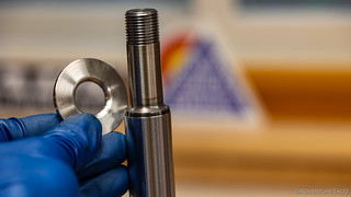
- Photograph the shock shaft assembly for future reference.
Shock shaft from a smooth body shock. 
Shock shaft from a coilover shock. - Remove the shaft nut. Note: this should take a bit of force, and it may be difficult to keep the shock shaft from spinning. If this is the case, an impact wrench can come in handy.
- Remove the shaft nut spacer.
- Remove the rebound shims, maintaining their order. Note that on OEM kits, these may be in a small holder.
- Remove the piston. Note: be careful at this point - the compression shims often stick to the bottom of the piston.
- Remove the compression shims, maintaining their order.
- Remove the washer that supports the compression shims.
- Remove any shaft spacers.
- Remove the internal shaft retainer.
- Remove the end cap.

Replacing Seals on the Internal Shaft Retainer
ADS has engineered a single-piece internal shaft retainer, with captured internal races that hold three seals to be replaced. It is quite a work of art, actually.
- Use a pick to remove the seal closest to the outer surface of the internal shaft retainer. Note its orientation on removal.
- Use a pick to remove the middle seal from the internal shaft retainer. Note its orientation on removal.
- Use a pick to remove the inner most seal (furthest from the outer surface) of the internal shaft retainer. Note its orientation on removal.
- Use a pick to remove the large o-ring on the outside of the internal shaft retainer.

- Clean up the internal shaft retainer, to remove all dirt and oil that might be present. Note: there is likely to be quite a bit of dirt in the races of the inner seals. Clean them thoroughly.
- Find the new seals/o-rings from the seal kit that match the existing seals you removed.
- Place a small amount of shock oil in a bowl so that you can dip each new seal/o-ring prior to installation.
- Install the three inner o-rings in the reverse order of removal, being careful to install them in the same orientation as they were removed. Note: this can be difficult, take your time to seat the seals correctly, once you get them started in their races, they will sort of "snap in" to place.
- Install the large o-ring onto the outside of the internal shaft retainer.

Replacing the Seals on the Shock Piston
- Use a pick to carefully remove the wear ring from the piston.

- Use a pick to remove the large o-ring on the outside of the piston.
- Clean up the piston, to remove all dirt and oil that might be present.
- Find the new seal from the seal kit that matches the existing seal you removed.
- Place a small amount of shock oil in a bowl so that you can dip each new seal/o-ring prior to installation.
- Install the large o-ring onto the outside of the piston.
- Reinstall the wear ring over the outside of the piston.

Inspecting and Cleaning the Shaft
- Inspect the shock shaft for straightness.
- Inspect the shock shaft for any chips or imperfections. If any are found, use an emory stone and some shock oil to lightly sand/polish the area to remove the imperfections. Note: do not use Emory cloth or sandpaper for this operation.
Assembling the Shock Shaft Assembly
- Spread a little shock oil on the shaft to assist with lubrication of the seals as they slide over the shaft.
- Slide the end cap onto the shaft.
- Slide the internal shaft retainer onto the shaft.
- Thread the internal shaft retainer and end cap together a little bit - not fully - just to keep them square on the shaft.
- If you removed shaft spacers, slide them onto the shaft.
- Slide the washer that supports the compression shims onto the shaft.
Note that the orientation of the washer is important. - Slide the compression shim stack onto the shaft.
- Note: the shims should generally form an inverted pyramid at this point, with the smaller shims toward the washer and the larger shims toward the piston.
- Note 2: if you are revalving your shocks at the same time as a rebuild, now is the time to ensure the correct order of your new compression shim stack.
- Slide the piston onto the shaft. Note: the side with more large holes should face up toward the rebound shims; the side with fewer large holes faces down toward the compression shims.
- Slide the rebound shim stack onto the shaft.
- Note: the shims should generally form a pyramid at this point, with the larger shims toward the piston.
- Note 2: if you are revalving your shocks at the same time as a rebuild, now is the time to ensure the correct order of your new rebound shim stack.
- Slide the shaft nut spacer onto the shaft.
- Reinstall the shaft nut. Note: if this is a locking nut in good shape, you can reuse it. If it is a non-locking nut, a small amount of blue loctite can be used.

Inserting the Internal Floating Piston into the Reservoir
- Spread a bit of shock oil onto the o-ring and wear band of the internal floating piston.
- Clamp the reservoir in a vise with the hose pointed down and with the opening facing up. Note: this may be difficult with the reservoir hose, but some strategic placement of supports will work.
- Position the wear band around the internal floating piston and use your fingers keep the wear band pressed against the piston as you carefully, and squarely, press the piston and wear band into the reservoir.

- Press the internal floating piston into the reservoir far enough for the o-ring to clear the threads on the reservoir housing.
- Use the Reservoir Piston Positioning Tool to push the internal floating piston all the way into the reservoir housing, until it bottoms out.
Filling the Reservoir with Oil
- Secure the shock in a vise with the opening facing up and the reservoir - and reservoir tube - hanging down. Note: this orientation is important so that as oil is added to the shock, it will flow down into the reservoir, allowing air bubbles to rise up through the oil and out of the shock.
- If it is not already, thread the Reservoir Piston Positioning Tool into the internal floating piston of the reservoir. Note: This will be used to cycle shock oil into the reservoir, and push air from the reservoir back out through the shock.

- If your reservoir has compression adjusters, be sure that they are fully open.
- Fill the shock approximately halfway with oil.
- Use the Reservoir Piston Positioning Tool to pull the internal floating piston toward the middle of the reservoir, drawing oil into the reservoir. Note: ensure that you don't draw more oil into the reservoir than you put in the shock body.
- Use the Reservoir Piston Positioning Tool to push the internal floating piston away from the middle of the reservoir, pushing air and oil out of the reservoir.
- Repeat steps 5 and 6 until no more air is being expelled from the reservoir.
- Use the Reservoir Piston Positioning Tool to pull the internal floating piston toward the middle of the reservoir, until the distance from the open end of the reservoir tube to the deepest part of the piston equals the measurement taken when disassembling the reservoir. Note: this is not the final positioning, which will be done later.
Inserting the Shock Shaft and Filling the Shock with Oil
This part of the operation can be a bit tricky. The idea is to get as much oil into the shock housing as possible, and to have no air bubbles.
- Move the end cap and internal shaft retainer as far down the shaft as possible (toward the rod end, away from the piston).

- Carefully seat the piston and wear band into the shock housing, just past the groove for the retaining ring.
- Press the shock shaft into the housing just until the piston reaches the oil level, and then continue pushing until it is just below the oil level. Note: some oil may jump up as it presses through the piston, so you may want to cover the shock tube opening with a towel.
- Cycle the piston up and down below the oil level several times to remove any trapped air/bubbles.
- Fill the shock housing with shock oil, to within 1.5 inches of being full.
- Pull the shock shaft up until the piston is at the oil level, but does not break the surface of the oil.
- Fill the shock housing with shock oil, to the level of the groove for the retaining ring.
- Slide the internal shaft retainer down toward the shock tube, just until the o-ring contacts the end of the tube.

- Holding the internal shaft retainer in place with one hand, slowly and carefully push the shock shaft down into the shock housing - displacing oil and any trapped air - until you see just a little bit of oil pressing up around the o-ring. Note: at this point, you've pushed all the air out of the shock.
- Use both hands to push the internal shaft retainer into the shock housing, just far enough to expose the retaining ring groove.
- Insert the retaining ring into the retaining ring groove.
- Pull the shock shaft out of the shock as far as possible, which will begin to pull the internal shaft retainer up toward the retaining ring.
- Use the Reservoir Piston Positioning Tool to push the internal floating piston further into the reservoir, pushing oil out of the reservoir and into the shock tubing. This will push the internal shaft retainer toward the retaining ring until it is seated.

- Measure the distance from the end of the reservoir tube to the deepest part of the piston. This should be approximately the same as your original measurement, with 1.5-2.5" of oil in the reservoir. Note: if the oil level is not correct, correct it before proceeding.
- Slide the end cap down the shock shaft and thread it onto the internal shaft retainer until it is snug, but do not fully tighten it yet - as the shock is not pressurized, it may continue to spin.
Replacing the End Cap on the Reservoir
- Spread some shock oil onto the two o-rings of the end cap, and thread the end cap into the reservoir. Tighten with the Shock / Reservoir Housing Wrench until just snug.
- Thread the valve core tool into the valve core on the end cap and pull the end cap back toward the end of the reservoir, until it is seated on the retaining ring.
- Reinstall the valve core in the Schrader valve housing.
Pressurizing the Shock and Securing the end cap
- Mentally go through a checklist to ensure that:
- You have a retaining ring in the shock housing.
- You don't have any spare parts that should have been installed.
- Fittings for hoses, etc. are tight.
- Set the regulator on your nitrogen tank to 100psi.
- Charge the reservoir with nitrogen. Note: you may notice the reservoir end cap and/or shock end cap move slightly at this point as they are fully seated by the pressure.
- Secure both end caps using the Shock / Reservoir Housing Wrench. Note: you want them to be tight, but not too tight
- Reinstall and secure the end cap set screw. Again, tight, but not overly so.

Pressure Testing and Final Pressurization
This process over pressurizes the shocks for a short period of time to ensure that there are no leaks before the final pressure is set and the shocks are put back into service.
- Set the regulator on your nitrogen tank to 350psi.
- Charge the shock with nitrogen.
- Allow the shock to sit on the bench for 24-48 hours, to ensure that no oil leaks out. Note: If oil does leak out, disassemble the shock and correct the issue.
- After the shocks have set for an extended period, if no oil has leaked out, check the pressure of the nitrogen in the reservoir. Note: this is a small volume of gas, so simply checking it will result in a significant drop in pressure. The reading should be similar to, but certainly lower than, the 350psi that was charged. Something in the 325psi range is reasonable.
- If there are no leaks, reduce the pressure to 200psi.

Your shocks are rebuilt and ready for another 50K miles of service.